Introduction
Interfacing a piezoelectric buzzer with an Arduino microcontroller is a simple yet powerful way to add sound and audio feedback to a wide range of projects. Piezoelectric buzzers are small and inexpensive devices that convert electrical energy into mechanical energy to produce sound. They are widely used in various applications, from industrial alarms and warning systems to consumer electronics, automotive, and home automation projects.
The Arduino microcontroller, on the other hand, is a popular development board that allows for easy programming and control of various devices and sensors. It has several digital and analog input/output pins that can be used to interface with external devices. Combining these two technologies, we can create a wide range of projects that require sound or audio feedback.
Hardware Components
You will require the following hardware for Interfacing Piezo Buzzer with Arduino.
| S.no | Component | Value | Qty |
|---|---|---|---|
| 1. | Arduino UNO | – | 1 |
| 2. | USB Cable Type A to B | – | 1 |
| 3. | Piezo Buzzer | – | 1 |
| 4. | Power Adapter for Arduino | 9V | 1 |
| 5. | Breadboard | – | 1 |
| 6. | Jumper Wires | – | 1 |
Piezo Buzzer with Arduino UNO
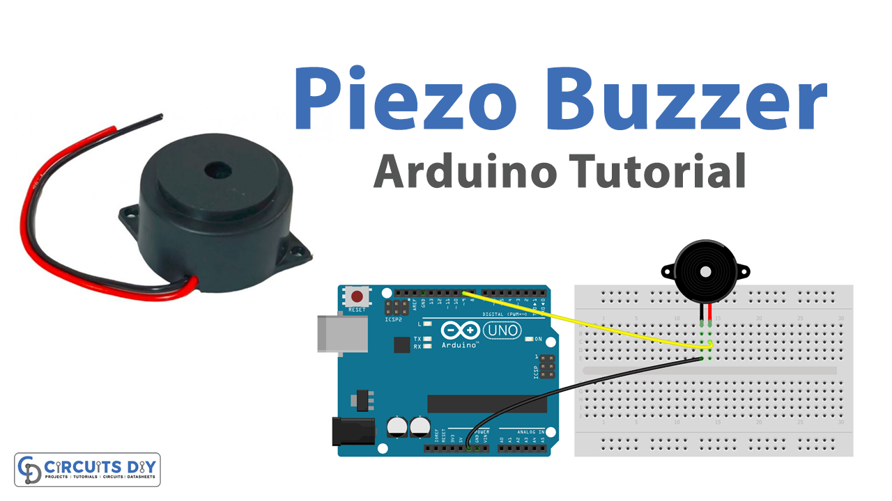
- Connect the positive lead of the piezoelectric buzzer to digital pin 8 of the Arduino UNO and the negative lead to GND.
- In the Arduino IDE, open a new sketch and include the following libraries:
#include <SoftwareSerial.h>
- Define the pin number for the piezoelectric buzzer:
const int buzzerPin = 8;
- In the setup() function, initialize the serial communication and set the pin mode for the piezoelectric buzzer as output:
Serial.begin(9600);
pinMode(buzzerPin, OUTPUT);
- In the loop() function, write a function to turn the piezoelectric buzzer on and off using the digitalWrite() function and print the status on the serial monitor using the Serial.println() function:
digitalWrite(buzzerPin, HIGH);
Serial.println("Buzzer is on");
delay(1000);
digitalWrite(buzzerPin, LOW);
Serial.println("Buzzer is off");
delay(1000);
- Upload the sketch to the Arduino UNO board
- Open the serial monitor and check the status of the buzzer.
Schematic
Make connections according to the circuit diagram given below.

Wiring / Connections
| Arduino | Buzzer |
|---|---|
| D8 | RED |
| GND | GND |
Installing Arduino IDE
First, you need to install Arduino IDE Software from its official website Arduino. Here is a simple step-by-step guide on “How to install Arduino IDE“.
Installing Libraries
Before you start uploading a code, download and unzip the following libraries at /Progam Files(x86)/Arduino/Libraries (default), in order to use the sensor with the Arduino board. Here is a simple step-by-step guide on “How to Add Libraries in Arduino IDE“.
- <a href=”http://” target=”_blank” rel=”noreferrer noopener”>pitches. h
Code
Now copy the following code and upload it to Arduino IDE Software.
Arduino Code
#include "pitches.h"
// notes in the melody:
int melody[] = {
  NOTE_C4, NOTE_G3, NOTE_G3, NOTE_A3, NOTE_G3, 0, NOTE_B3, NOTE_C4
};

// note durations: 4 = quarter note, 8 = eighth note, etc.:
int noteDurations[] = {
  4, 8, 8, 4, 4, 4, 4, 4
};

void setup() {
  // iterate over the notes of the melody:
  for (int thisNote = 0; thisNote < 8; thisNote++) {

    // to calculate the note duration, take one second divided by the note type.
    //e.g. quarter note = 1000 / 4, eighth note = 1000/8, etc.
    int noteDuration = 1000 / noteDurations[thisNote];
    tone(8, melody[thisNote], noteDuration);

    // to distinguish the notes, set a minimum time between them.
    // the note's duration + 30% seems to work well:
    int pauseBetweenNotes = noteDuration * 1.30;
    delay(pauseBetweenNotes);
    // stop the tone playing:
    noTone(8);
  }
}

void loop() {
  // no need to repeat the melody.
}
Modifying Arduino Code
#include "pitches.h"

// notes in the melody:
int melody[] = {
  NOTE_E5, NOTE_E5, NOTE_E5,
  NOTE_E5, NOTE_E5, NOTE_E5,
  NOTE_E5, NOTE_G5, NOTE_C5, NOTE_D5,
  NOTE_E5,
  NOTE_F5, NOTE_F5, NOTE_F5, NOTE_F5,
  NOTE_F5, NOTE_E5, NOTE_E5, NOTE_E5, NOTE_E5,
  NOTE_E5, NOTE_D5, NOTE_D5, NOTE_E5,
  NOTE_D5, NOTE_G5
};

// note durations: 4 = quarter note, 8 = eighth note, etc, also called tempo:
int noteDurations[] = {
  8, 8, 4,
  8, 8, 4,
  8, 8, 8, 8,
  2,
  8, 8, 8, 8,
  8, 8, 8, 16, 16,
  8, 8, 8, 8,
  4, 4
};

void setup() {
  // iterate over the notes of the melody:
  int size = sizeof(noteDurations) / sizeof(int);

  for (int thisNote = 0; thisNote < size; thisNote++) {

    // to calculate the note duration, take one second divided by the note type.
    //e.g. quarter note = 1000 / 4, eighth note = 1000/8, etc.
    int noteDuration = 1000 / noteDurations[thisNote];
    tone(8, melody[thisNote], noteDuration);

    // to distinguish the notes, set a minimum time between them.
    // the note's duration + 30% seems to work well:
    int pauseBetweenNotes = noteDuration * 1.30;
    delay(pauseBetweenNotes);
    // stop the tone playing:
    noTone(8);
  }
}

void loop() {
  // no need to repeat the melody.
}
Working Explanation
In the setup() function, the serial communication is initialized by calling Serial.begin(9600) and the pin mode for the piezoelectric buzzer is set as an output by calling pinMode(buzzerPin, OUTPUT). In the loop() function, the code uses the digitalWrite(buzzerPin, HIGH) function to turn the piezoelectric buzzer on and the digitalWrite(buzzerPin, LOW) function to turn it off. The Serial.println("Buzzer is on") and Serial.println("Buzzer is off") are used to print the status of the buzzer on the serial monitor.
The delay(1000) function is used to pause the execution of the loop for 1 second, which creates the effect of the buzzer turning on and off with a 1-second delay. This allows the user to monitor the status of the buzzer in real time through the serial monitor.
Applications
- Industrial alarm systems
- Home automation
- Robotics
- Automotive warning signals
- Consumer electronics
Conclusion.
We hope you have found this Arduino Piezo Buzzer Circuit very useful. If you feel any difficulty in making it feel free to ask anything in the comment section.