Introduction
Heartbeats, the rhythm of life. They’re a constant reminder of our mortality but also a symbol of vitality. Imagine being able to track your heart’s health with precision and ease to have a better understanding of your body and its needs. With the use of an Arduino microcontroller and a heart rate sensor module, this is now possible. These small yet powerful tools can give you real-time data on your heart rate, allowing you to keep a close eye on your cardiovascular health.
You can track your heart rate, but with some programming knowledge, you can also use the Arduino and sensor module to create interactive projects. Imagine creating a fitness tracker, a stress monitoring device, or even a game that responds to your heart rate. The possibilities are endless, and with this guide, you’ll learn how to interface the sensor module with Arduino and how to read and interpret the data it provides. So whether you’re a health enthusiast, a maker, or just curious about the inner workings of your heart, this guide is for you.
What is Heart Rate Sensor?
An electronic device that detects and displays a person’s heart rate, most often in terms of beats per minute, is referred to as a “heart rate sensor.” There are many other names for it, including electrocardiogram monitor and heart monitor.

Hardware Components
You will require the following hardware for Interfacing Heart Rate Sensor Module with Arduino.
| S.no | Component | Value | Qty |
|---|---|---|---|
| 1. | Arduino UNO | – | 1 |
| 2. | Heart Rate Sensor Module | – | 1 |
| 3. | Breadboard | – | 1 |
| 4. | Jumper Wires | – | 1 |
Heart Rate Sensor Module with Arduino
Now that you have an idea of what a heart rate sensor is, it’s time to interface it with Arduino. And for this, you need to follow the given steps:
Schematic
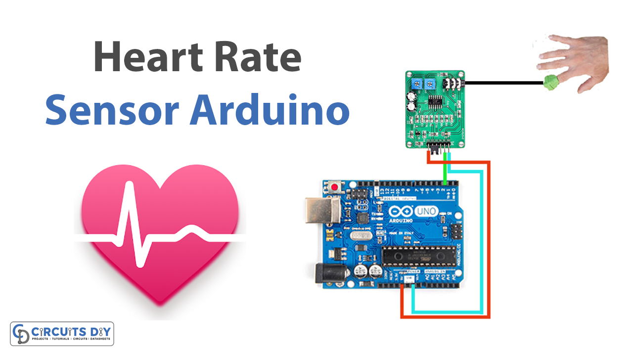
Make connections according to the circuit diagram given below.

Wiring / Connections
| Arduino | Heart Rate Sensor |
|---|---|
| 5V | VCC |
| GND | GND |
| D2 | D0 |
Installing Arduino IDE
First, you need to install Arduino IDE Software from its official website Arduino. Here is a simple step-by-step guide on “How to install Arduino IDE“.
Installing Libraries
Before you start uploading a code, download and unzip the following libraries at /Progam Files(x86)/Arduino/Libraries (default), in order to use the sensor with the Arduino board. Here is a simple step-by-step guide on “How to Add Libraries in Arduino IDE“.
Code
Now copy the following code and upload it to Arduino IDE Software.
int pulse = 2;
int current_ms = 0;
int inter_num = 0;
int last_ms;
int x;
int heart_per_min;
int  arr[10] = {0, 0, 0, 0, 0, 0, 0, 0, 0, 0};
void setup()
{
  Serial.begin(9600);
  pinMode(pulse, INPUT);
  attachInterrupt(0, pulse_num, RISING );
  last_ms = millis();
}

void loop()
{
  if (arr[0] != 0) {
    Serial.print("heart_per_min:   ");
    Serial.println(heart_per_min);
    heart_per_min=0;
  }
  Serial.println("wait ");
  delay(10000);
}

void pulse_num()
{
  inter_num++;
  if (inter_num == 9) {
    inter_num = 0;
  }

  float sum = 0.00;
  current_ms = millis();
  x = current_ms - last_ms;

  last_ms = millis();
  for (int i = 0; i < 9; i++) {
    arr[i] = arr[i + 1];
  }
  arr[9] = x;
  for (int i = 0; i < 10; i++) {
    sum += arr[i];
  }
  sum = sum / 10.00;
  heart_per_min = (60000.00)/sum;

}
Let’s Test It
Open the Serial Monitor in the Arduino IDE once the code has been sent to the Arduino board. You should see the message “wait” printed, and then, after 10 seconds, the heart rate is in beats per minute. Place the pulse sensor on your finger or earlobe and observe the heart rate displayed on the serial monitor. It will print the heart rate every 10 seconds.
Working Explanation
The above code measures the heart rate of a person. It does this by using an interrupt to count the times a pulse sensor sends a signal.
First, it declares some variables:
- “pulse” is set to 2, which is the pin number of the pulse sensor.
- “current_ms” and “last_ms” are used to keep track of the time between each pulse.
- “inter_num” is the number of interrupts that have occurred.
- “x” is the time difference between the current and last pulse.
- “heart_per_min” is the calculated heart rate.
- “arr” is an array that stores the last 10 time differences between pulses.
In the void setup(), the serial communication is started, the pulse sensor pin is set to input, and an interrupt is attached to pin 0 to trigger the “pulse_num()” function when a rising signal is detected. The current time is also stored in “last_ms.”
In the void loop(), the code checks if a value is stored in the first element of the “arr” array; if yes, it prints the heart rate and resets it to zero. Then it will wait for 10 sec and repeat the process. The pulse_num() function is triggered every time a rising signal is detected on the pulse sensor pin. It increments the “inter_num” variable, and if it reaches 9, it resets it back to 0. It then calculates the difference between the current and last pulse, stores that value in the “arr” array and calculates the average of the last 10 time differences. Using this average, the code calculates the heart rate in beats per minute.
Applications
- Heart rate monitoring devices
- Stress monitoring
- Health tracking devices, etc
Conclusion.
We hope you have found this Interfacing Heart Rate Sensor Module with Arduino Circuit very useful. If you feel any difficulty in making it feel free to ask anything in the comment section.


