Introduction
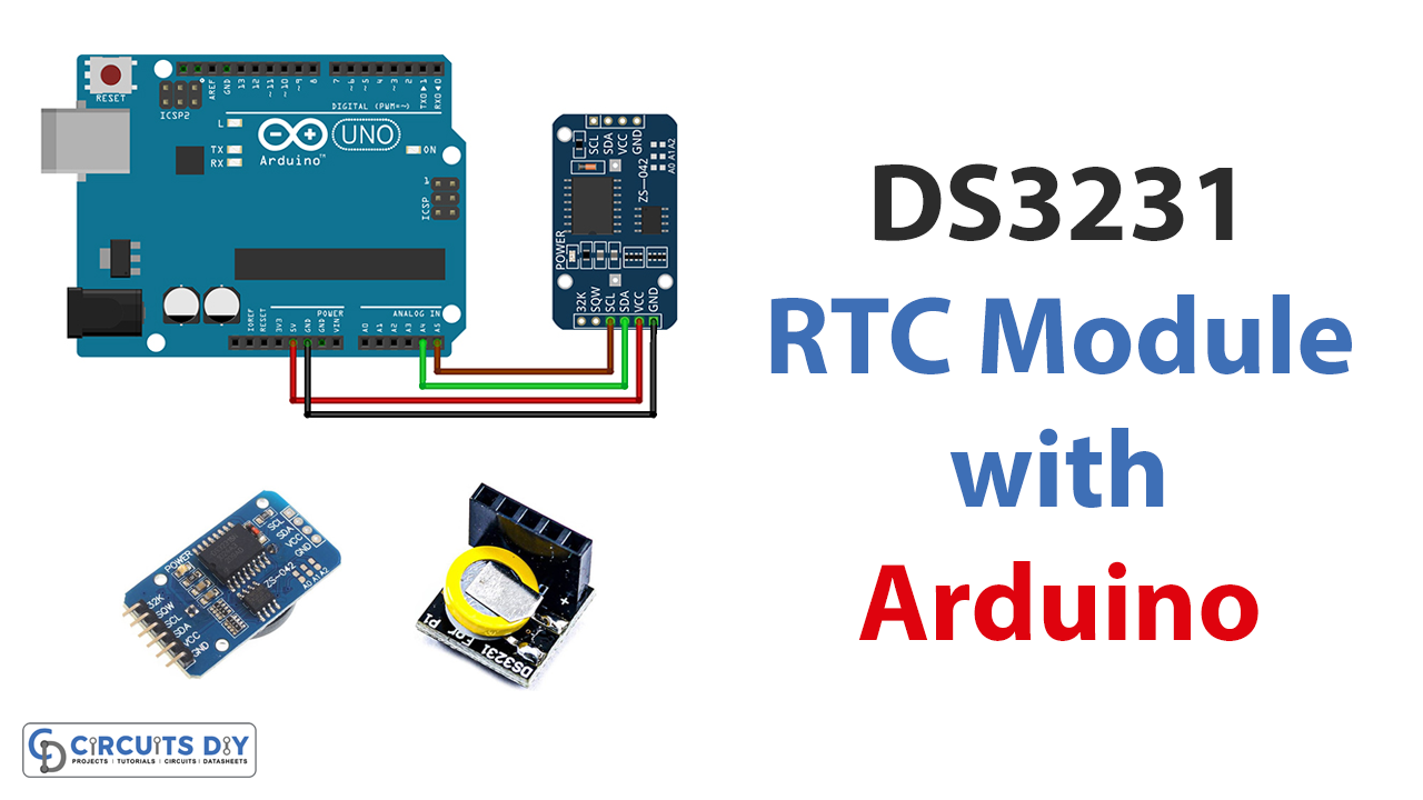
This tutorial is Interfacing DS3231 Real Time Clock RTC Module with Arduino!
People often use the need to know the exact time as a trigger for specific actions, like turning on a device or turning off an alarm clock. For that purpose, devices used RTCs. Real-time clocks (RTC) get their power from a separate source from the primary device. This makes tracking more accurate and prevents data loss. Some RTCs are intended to be put inside a device’s microcontroller unit; however, most RTCs do not have this design feature.
Even if the external power supply is turned off, real-time clocks inside an embedded system may still be able to measure time accurately. It keeps track of the hours, minutes, and seconds, as well as the months, days, and even years. You can find these modules in almost every digital electronic device, especially ones that need to keep accurate time.
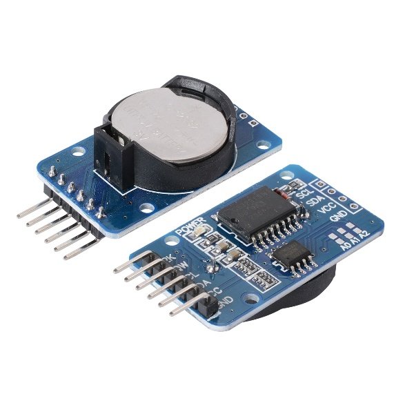
DS3231 Real Time Clock RTC Module
DS3231 real-time clock (RTC) module assists in many applications that call for precise timing. To set the correct time and date on the RTC, you need to write code that communicates to it through the I2C connection and gives it the proper instructions. After establishing the time and date, you may utilize the RTC to keep track of the time in the future.
Hardware Components
You will require the following hardware for Interfacing DS3231 Real Time Clock RTC Module with Arduino.
| S.no | Component | Value | Qty |
|---|---|---|---|
| 1. | Arduino UNO | – | 1 |
| 2. | I2C Real Time Clock Module | DS3231 | 1 |
| 3. | Real-Time Clock Module | DS3231 | 1 |
| 4. | Breadboard | – | 1 |
| 5. | Jumper Wires | – | 1 |
DS3231 Real Time Clock RTC Module with Arduino
Now that you have the required components and you have understood the DS3231 Real Time Clock RTC Module, you need to follow the given steps:
Schematic
Make connections according to the circuit diagram given below.

Wiring / Connections
| Arduino | RTC I2C DS3231 | RTC DS3231 |
|---|---|---|
| 5V | VCC | VCC |
| GND | GND | GND |
| A4 | SDA | SDA |
| A5 | SCL | SCL |
Installing Arduino IDE
First, you need to install Arduino IDE Software from its official website Arduino. Here is a simple step-by-step guide on “How to install Arduino IDE“.
Installing Libraries
Before you start uploading a code, download and unzip the following libraries at /Progam Files(x86)/Arduino/Libraries (default) in order to use the sensor with the Arduino board. Here is a simple step-by-step guide on “How to Add Libraries in Arduino IDE“.
Code
Now copy the following code and upload it to Arduino IDE Software.
#include <Wire.h>
#include <ds3231.h>

struct ts t;

void setup() {
  Serial.begin(9600);
  Wire.begin();
  DS3231_init(DS3231_CONTROL_INTCN);
  /*----------------------------------------------------------------------------
In order to synchronize your clock module, insert the timetable values below!
  ----------------------------------------------------------------------------*/
  t.hour=3;
  t.min=0;
  t.sec=0;
  t.mday=14;
  t.mon=11;
  t.year=2020;

  DS3231_set(t);
}

void loop() {
  DS3231_get(&t);
  Serial.print("Date : ");
  Serial.print(t.mday);
  Serial.print("/");
  Serial.print(t.mon);
  Serial.print("/");
  Serial.print(t.year);
  Serial.print("\t Hour : ");
  Serial.print(t.hour);
  Serial.print(":");
  Serial.print(t.min);
  Serial.print(".");
  Serial.println(t.sec);

  delay(1000);
}
Let’s Test It
It’s now time to test the circuit. Once you complete the wiring and upload the code, the code will start working. Once the initial time parameters, such as the second, minute, day, month, year, and century, are set, the module starts to work and is updated every second. The data from the module is seen on the Serial Monitor.
Working Explanation
To understand the working explanation of the circuit, we need to dig a little bit into the code:
- First, we include the required libraries in the code.
- In the void setup function, we initialize the serial monitor using Serial.begin. Then we initialize the I2C bus using the Wire library, and after that, we initialize the DS3231 RTC module using the DS3231_init() function.
- Next, the code sets the time on the DS3231 RTC module using the DS3231_set() function. This function takes a structure of type “ts” as an argument, which contains the time and date information to be set.
- In the void loop function, the code reads the current time and date from the DS3231 RTC module using the DS3231_get() function.
- The code then prints the date and time to the serial monitor. The date is printed in the format “day/month/year“, and the time is printed in the format “hour:minute:second“.
- Finally, the code uses the delay() function to pause for 1 second before repeating the process.
Applications
- Alarms and clock
- To display the current time and date.
- Data logging and time synchronization, etc
Conclusion.
We hope you have found this “Interfacing DS3231 Real Time Clock RTC Module with Arduino Circuit” very useful. If you have any difficulty making it, feel free to ask anything in the comment section.


