Introduction
Are you tired of limited range and interference with your wireless communication projects? The APC220 module is here to help! This small, cheap RF transceiver makes it easy to send and receive data wirelessly up to several hundred meters away. This tutorial will show you how to set up and use the APC220 module with an Arduino board and how to send and receive data wirelessly.
By the end of this tutorial, you’ll be able to wirelessly transmit data from one device to another, opening up a whole new world of possibilities for your projects. So let’s get started and take your wireless communication skills to the next level with the APC220 RF transceiver module and Arduino!
What is RF Transceiver Module?
RF transceiver modules are devices that transmit or receive a radio frequency signal. They may also do both of these functions simultaneously. Most RF transceiver modules work within a specific range of frequencies and follow a specific wireless protocol. They can send and receive data over short distances, usually within a few hundred meters.
Hardware Components
You will require the following hardware for Interfacing APC220 RF Transceiver Module with Arduino.
| S.no | Component | Value | Qty |
|---|---|---|---|
| 1. | Arduino UNO | – | 1 |
| 2. | Communication Module | APC220 | 1 |
| 3. | Breadboard | – | 1 |
| 4. | Jumper Wires | – | 1 |
APC220 RF Transceiver Module with Arduino
Once you have all the components, follow the given steps:
Schematic
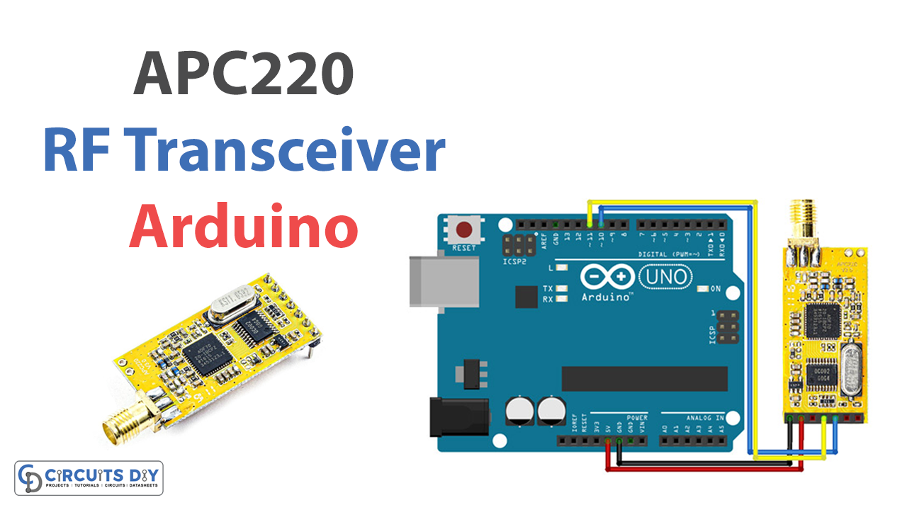
Make connections according to the circuit diagram given below.

Wiring / Connections
| Arduino | Communication Module |
|---|---|
| 5V | VCC |
| GND | GND |
| D10 | RX |
| D11 | TX |
Installing Arduino IDE
First, you need to install Arduino IDE Software from its official website Arduino. Here is a simple step-by-step guide on “How to install Arduino IDE.”
Installing Libraries
Before you start uploading code, download and unzip the following libraries at /Program Files (x86)/Arduino/Libraries (default) in order to use the sensor with the Arduino board. Here is a simple step-by-step guide on “How to Add Libraries in Arduino IDE“.
Code
Now copy the following code and upload it to Arduino IDE Software.
#include <SoftwareSerial.h>

SoftwareSerial mySerial(10, 11); // RX, TX

void setup() {
Open serial communications and wait for the port to open:
  Serial.begin(9600);
  while (!Serial) {
    ; // wait for serial port to connect. Needed for native USB port only
  }

  // set the data rate for the SoftwareSerial port
  mySerial.begin(9600);
}

void loop() { // run over and over
  if (mySerial.available()) {
    Serial.write(mySerial.read());
  }
  if (Serial.available()) {
    mySerial.write(Serial.read());
  }
}
Let’s Test It
Its now time to test the circuit. Once you make the circuit and upload the code, the circuit will start receiving or transmitting the data according to the given code.
Working Explanation
To get a proper understanding of the circuit, you need to understand the code.
The code sets up a SoftwareSerial connection with the Arduino board using pins 10 and 11 for RX and TX respectively. The void setup() function initializes serial communication with the computer at a baud rate of 9600 and then sets up the SoftwareSerial connection with the same baud rate. The void loop() function continuously checks if there is data available on either the SoftwareSerial or the native serial connection. If data is available, it is written to the other serial connection. This allows data to be transmitted and received between the Arduino board and the computer through both the native serial connection and the SoftwareSerial connection.
Applications
- Home and industrial automation
- Wireless network
- Data logging, etc.
Conclusion.
We hope you have found this “Interfacing APC220 RF Transceiver Module with Arduino Circuit” very useful. If you have any difficulty making it, feel free to ask anything in the comment section.