Introduction
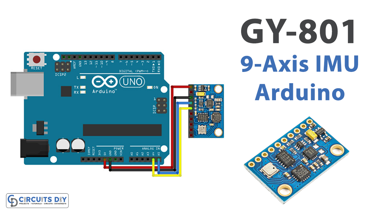
In this article, you will see an Interfacing 9-Axis GY-801 IMU Module with Arduino. You can use the accelerometer to measure the acceleration of the module, or you can use the gyroscope to measure the angular velocity of the module. You can the magnetometer data to measure the local magnetic field. But, what if you use only one module that includes them all? Yes! it is GY-801.
To interface the GY-801 module with an Arduino, you will need to connect the module to the Arduino board using wires and possibly a breadboard. You will then need to use the Arduino programming language to read the sensor data from the module. This typically involves setting up the necessary libraries, initializing the sensors, and writing code to read and interpret the sensor data.
9-Axis GY-801 IMU Module
Interfacing a 9-axis IMU module (such as the GY-801) with an Arduino involves connecting the module to the Arduino board and using the Arduino programming language to read and interpret the sensor data.
The GY-801 module contains several sensors: a 3-axis accelerometer, a 3-axis gyroscope, and a 3-axis magnetometer. These sensors can measure various physical quantities, including acceleration, angular velocity, and the strength and direction of the local magnetic field.

Hardware Components
You will require the following hardware for Interfacing 9-Axis GY-801 IMU Module with Arduino.
| S.no | Component | Value | Qty |
|---|---|---|---|
| 1. | Arduino UNO | – | 1 |
| 2. | Module | GY-801 | 1 |
| 3. | Breadboard | – | 1 |
| 4. | Jumper Wires | – | 1 |
Interfacing 9-Axis GY-801 IMU Module with Arduino
Get all the required components that are listed above in the hardware section. Once you have them all, follow the given steps:
Schematic
Make connections according to the circuit diagram given below.

Wiring / Connections
| Arduino | GY-801 Module |
|---|---|
| 5V | VCC |
| GND | GND |
| A4 | SDA |
| A5 | SCL |
Installing Arduino IDE
First, you need to install Arduino IDE Software from its official website Arduino. Here is a simple step-by-step guide on “How to install Arduino IDE“.
Installing Libraries
Before you start uploading a code, download and unzip the following libraries at /Progam Files(x86)/Arduino/Libraries (default), in order to use the sensor with the Arduino board. Here is a simple step-by-step guide on “How to Add Libraries in Arduino IDE“.
Code
Now copy the following code and upload it to Arduino IDE Software.
#include <Arduino.h>
#include "Wire.h"
#include "MMC5883.h"
#include <I2Cdev.h>
#include "L3G4200D.h"
#include "ADXL345.h"
#include <Adafruit_Sensor.h>
#include "Adafruit_BMP085_U.h"


L3G4200D gyro;
ADXL345 accel;
MMC5883MA MMC5883(Wire);
Adafruit_BMP085_Unified bmp = Adafruit_BMP085_Unified(10085);

int16_t ax, ay, az;
int16_t avx, avy, avz;
double baseline; // baseline pressure

void setup()
{
  Serial.begin(9600);
  Wire.begin();

  Serial.println("Initializing I2C devices...");
  gyro.initialize();
  accel.initialize();

  // verify connection
  Serial.println("Testing device connections...");
  Serial.println(gyro.testConnection() ? "L3G4200D connection successful" : "L3G4200D connection failed");
  Serial.println("Testing device connections...");
  Serial.println(accel.testConnection() ? "ADXL345 connection successful" : "ADXL345 connection failed");

  // data seems to be best when full scale is 2000
  gyro.setFullScale(2000);

  if (!bmp.begin())
    Serial.print("Ooops, no BMP085 detected ... Check your wiring or I2C ADDR!");

Serial.print("MMC5883MA ");
  MMC5883.begin();
  MMC5883.calibrate();
}

void loop()
{

  Serial.print(MMC5883.readData());

  Serial.print("     ");
  gyro.getAngularVelocity(&avx, &avy, &avz);

  Serial.print("gyro X:");
  Serial.print(avx);
  Serial.print("\tY:");
  Serial.print(avy);
  Serial.print("\tZ:");
  Serial.print(avz);
  // read raw accel measurements from device
  accel.getAcceleration(&ax, &ay, &az);

  // display tab-separated accel x/y/z values
  Serial.print("\taccel X:");
  Serial.print(ax);
  Serial.print("\tY:");
  Serial.print(ay);
  Serial.print("\tZ:");
  Serial.print(az);
  /* Get a new sensor event */
  sensors_event_t event;
  bmp.getEvent(&event);

  /* Display the results (barometric pressure is measure in hPa) */
  if (event.pressure)
  {
    /* Display atmospheric pressue in hPa */
    Serial.print("\tPressure:");
    Serial.print(event.pressure);
    Serial.print(" hPa");

    /* First we get the current temperature from the BMP085 */
    float temperature;
    bmp.getTemperature(&temperature);
    Serial.print("\tTemp:");
    Serial.print(temperature);
    Serial.print(" C");

    /* Then convert the atmospheric pressure, and SLP to altitude         */
    /* Update this next line with the current SLP for better results      */
    float seaLevelPressure = SENSORS_PRESSURE_SEALEVELHPA;
    Serial.print("\tAltitude:");
    Serial.println(bmp.pressureToAltitude(seaLevelPressure,
                                        event.pressure));
  }
  else
  {
    Serial.println("BME Sensor error");
  }
  delay(1000);
 }
Let’s Test It
It’s now time to test the circuit. Once you upload the code, open the serial monitor and it will show you the readings of angular velocity, acceleration, temperature, pressure, etc
Working Explanation
As you know, GY-801 10DOF IMU includes sensor L3G4200D, ADXL345, HMC5883L, and BMP180. Therefore, this Arduino sketch uses various sensors to measure various physical quantities. The sensors used in this sketch are:
L3G4200D gyroscope: This sensor measures angular velocity in three dimensions (x, y, and z).
ADXL345 accelerometer: This sensor measures acceleration in three dimensions (x, y, and z).
MMC5883 magnetometer: This sensor measures the strength and direction of the local magnetic field.
Adafruit BMP085 barometric pressure sensor: This sensor measures atmospheric pressure and temperature.
- The sketch begins by including the necessary libraries and initializing the sensors. It then sets up a serial connection to the computer and prints some messages to indicate the status of the sensor connections. The gyroscope and accelerometer are configured with a full-scale range of 2000. The magnetometer is calibrated using the calibrate() function.
- In the void loop() function, the sketch reads data from all four sensors and prints it out to the serial port. The magnetometer data is printed first, followed by the gyroscope data, the accelerometer data, and the barometric pressure and temperature data. The program then waits for one second before repeating the process.
Applications
- Gaming devices
- Virtual reality input devices
- Vibration monitoring
- GPS navigation systems
- Robotic
- Weather stations, etc
Conclusion.
We hope you have found this Interfacing 9-Axis GY-801 IMU Module with Arduino Circuit very useful. If you feel any difficulty in making it feel free to ask anything in the comment section.