Introduction
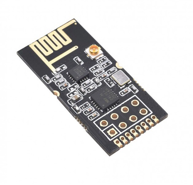
As the name implies, the transceiver is the combination of transmitter and receiver. In radio communication and electronics, it’s a device that transfers and receives the information of data. Before the 1920s the transmitter and receiver were designed separately. But, nowadays it’s widely used in wireless communication. And, for this purpose embedded systems are using the RF transceiver modules. Therefore, In this tutorial, we are going to interface “nRF24L01 – 2.4GHz RF Transceiver Module with Arduino UNO”.
Working Principle of RF Transceiver Module
RF Transceiver is made from amplifiers, mixers, RF components, etc. RF transceiver has a transmitter and receiver in it. A transmitter transfers and modulates the RF waves. A receiver then obtains modulated waves to demodulate them. The two types of receivers are in the market. First, a super-regenerative, a low power receives. They are inexpensive but also inaccurate. Second, superheterodyne, high-performance receivers. Also, they are more stable with voltage and temperature.
Specifications nRF24L01
- The operating voltage is 3.3 V
- It draws the maximum current of 250mA
- Its Communication protocol is SPI
- Its antenna range is 250Kb
- It consumes low power
- Inexpensive and affordable
Hardware Required
| S.no | Component | Value | Qty |
|---|---|---|---|
| 1. | Arduino | UNO | 1 |
| 2. | USB Cable Type A to B | – | 1 |
| 3. | Jumper Wires | – | – |
| 4. | RF Transceiver Module | nRF24L01 – 2.4GHz | – |
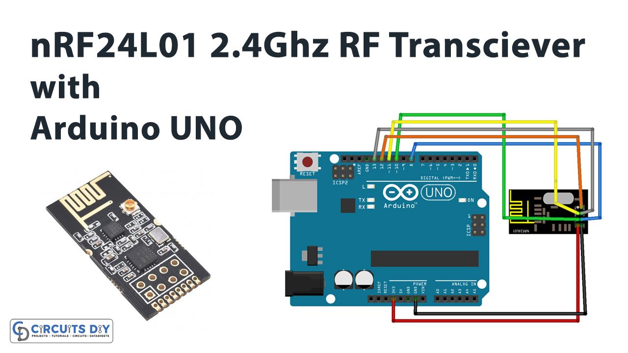
Circuit Diagram
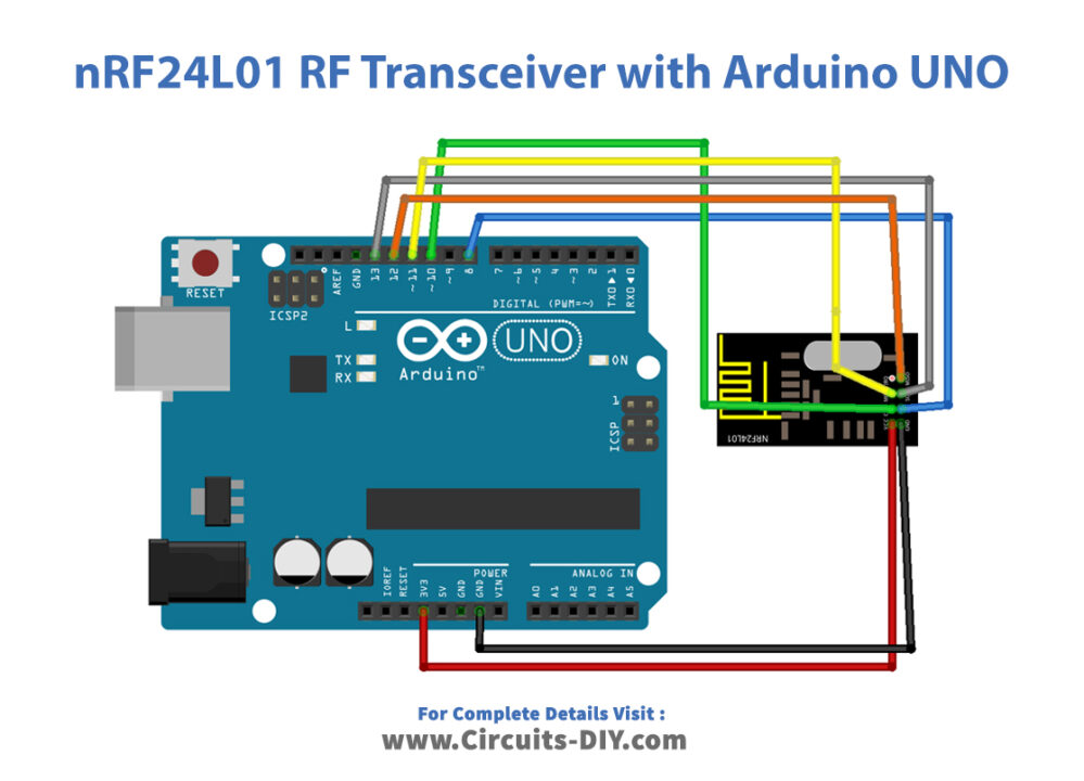
Connection Table
| Arduino | nRF24L01 – 2.4GHz RF Transceiver Module |
|---|---|
| VCC | VCC |
| GND | GND |
| D13 | SCK |
| D12 | MISO |
| D11 | MOSI |
| D10 | CSN |
| D8 | CE |
Arduino Code
// Circuits DIY
 // For Complete Details Visit -> https://circuits-diy.com
// nrf24_client

#include <SPI.h>
#include <RH_NRF24.h>

// Singleton instance of the radio driver
RH_NRF24 nrf24;
// RH_NRF24 nrf24(8, 7); // use this to be electrically compatible with Mirf
// RH_NRF24 nrf24(8, 10);// For Leonardo, need explicit SS pin
// RH_NRF24 nrf24(8, 7); // For RFM73 on Anarduino Mini

void setup()
{
  Serial.begin(9600);
  while (!Serial)
    ; // wait for serial port to connect. Needed for Leonardo only
  if (!nrf24.init())
    Serial.println("init failed");
  // Defaults after init are 2.402 GHz (channel 2), 2Mbps, 0dBm
  if (!nrf24.setChannel(1))
    Serial.println("setChannel failed");
  if (!nrf24.setRF(RH_NRF24::DataRate2Mbps, RH_NRF24::TransmitPower0dBm))
    Serial.println("setRF failed");
}


void loop()
{
  Serial.println("Sending to nrf24_server");
  // Send a message to nrf24_server
  uint8_t data[] = "Hello World!";
  nrf24.send(data, sizeof(data));

  nrf24.waitPacketSent();
  // Now wait for a reply
  uint8_t buf[RH_NRF24_MAX_MESSAGE_LEN];
  uint8_t len = sizeof(buf);

  if (nrf24.waitAvailableTimeout(500))
  {
    // Should be a reply message for us now
    if (nrf24.recv(buf, &len))
    {
      Serial.print("got reply: ");
      Serial.println((char*)buf);
    }
    else
    {
      Serial.println("recv failed");
    }
  }
  else
  {
    Serial.println("No reply, is nrf24_server running?");
  }
  delay(400);
}
Working Explanation
Assemble nRF24L01 – 2.4GHz RF Transceiver Module With Arduino UNO according to the diagram above. Upload the above-mentioned code in your Arduino. In the code, you can see that client is sending the message Hello world to the server. The server replying got a reply. And, show this on a Serial monitor.
Code Explanation
- Install and download the RadioHeadLibraray. You can download the library from:
- Include this library. Also, include the SPI library to communicate with the transceiver.
- In void setup, the code has initialized the Serial Monitor.
- In a void loop, there are functions to send the data. And, then there is a function to wait for the packet received. After that conditions are applied if the transceiver got the reply, or gets failed.
Application and Uses
- It can be used for wireless communication
- Also, to alter RF frequencies to IR frequencies or IR to RF frequencies.
- For the transmission of the television signal
- Moreover, it is used for satellite communication.


