Introduction
The motors perform an influent irregularity of electronic circuits and mechanical equipment. Every machine uses servo motors on a regular basis, and it is extensively employed in mechanical and automation applications. These motors are also having a significant role in robotics, which led to their being used in complex mechanical applications. There are several types of servo motors on the market. In this tutorial, we are going to Interface MG995 Servo Motor with Arduino.
MG995 Servo Motor
Because of its effectiveness and affordability, the servo motor MG995 is well-liked. Numerous uses of the motor are found in robotics and drone technology. Also, this servo motor is an example of a torque servo having a degree of rotation in the 180o range.
Pin Configuration
| Pin | Color | Name | Function |
| 1 | Orange | Signal pin | The PWM signal which states the axis position is given through this pin. |
| 2 | Red | VCC | A positive power supply for the servo motor is given to this pin. |
| 3 | Brown | Ground | This pin is connected to the ground of the circuit or power supply. |
Hardware Required
| S.no | Component | Value | Qty |
|---|---|---|---|
| 1. | Arduino UNO | – | 1 |
| 2. | USB Cable Type A to B | – | 1 |
| 3. | Servo Motor | MG995 | 1 |
| 4. | Jumper Wires | – | – |
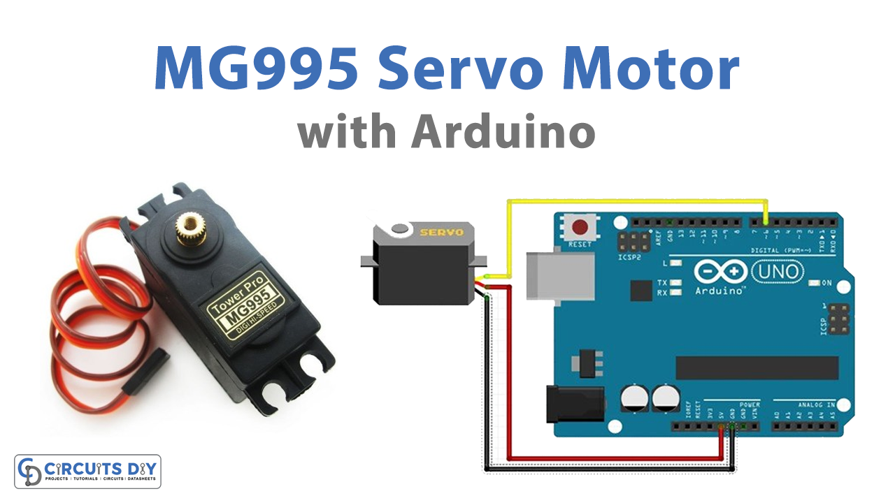
Circuit Diagram

Connection Table
| Arduino UNO | MPU9250 9-DOF MEMS Sensor Module |
|---|---|
| GND | GND (Brown) |
| 3.3v | Vcc (Red) |
| D6 | PWM Signal (Orange) |
Arduino Code
/* This example Arduino Sketch controls the complete rotation of
 *  SG995 Servo motor by using its PWM and Pulse width modulation technique
 */

#include <Servo.h> // include servo library to use its related functions
#define Servo_PWM 6 // A descriptive name for D6 pin of Arduino to provide PWM signal
Servo MG995_Servo;  // Define an instance of of Servo with the name of "MG995_Servo"


void setup() {
  Serial.begin(9600); // Initialize UART with 9600 Baud rate
  MG995_Servo.attach(Servo_PWM);  // Connect D6 of Arduino with PWM signal pin of servo motor

}

void loop() {
  Serial.println("0");// You can display on the serial the signal value
  MG995_Servo.write(0); //Turn clockwise at high speed
  delay(3000);
  MG995_Servo.detach();//Stop. You can use deatch function or use write(x), as x is the middle of 0-180 which is 90, but some lack of precision may change this value
  delay(2000);
  MG995_Servo.attach(Servo_PWM);//Always use attach function after detach to re-connect your servo with the board
  Serial.println("0");//Turn left high speed
  MG995_Servo.write(180);
  delay(3000);
  MG995_Servo.detach();//Stop
  delay(2000);
  MG995_Servo.attach(Servo_PWM);


}
Working Explanation
To Interface MG995 Servo Motor with Arduino, first, make connections according to the diagram given above. Copy the above code and upload it to your Arduino IDE. After that, upload the code and observe the rotation of the servo motor.
Code Explanation
- Install the “Servo.h” servo motor library and include it in the code. The pin is then defined. The motor’s signal pin was wired to Arduino’s PWM pin 6. Create objects of the servo library functions, MG995 Servo.
- The void setup section starts the Serial communication at the usual baud rate of 9600 bits per second. Furthermore, it connects the MG995 Servo object to pin 6.
- The code in the void loop rotates the motor clockwise first, then anticlockwise. When the myservowrite(0) command is run, the motor begins to rotate from the right side for a short period of time before stopping for 2000 milliseconds. Detaches the instance as well to lessen motor noise. Similarly, when myservowrite(180) is called, the motor rotates in an anticlockwise manner for 2000 milliseconds before stopping.
Application and Uses
- Robotics and drones
- Industrial machines
- Cameras
- Solar positioning, etc