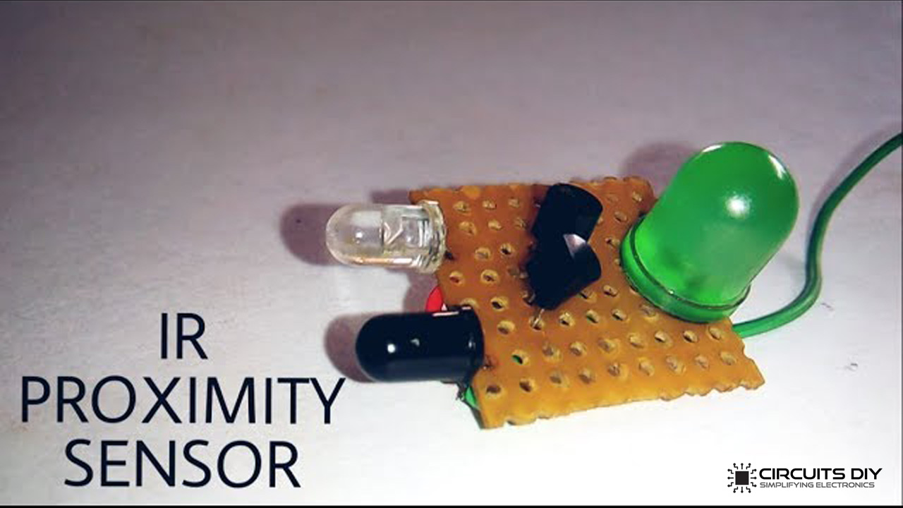
IR sensors or infrared proximity sensors are dedicated sensors that can detect the presence of another object without any physical contact. Infrared proximity sensors have high operational life due to the absence of mechanical parts. So, in this project, we are going to design a simple Infrared Proximity Sensor circuit Using NPN Transistors.
IR proximity sensor functions by sending a voltage to IR light-emitting diodes (LEDs) which in turn, emit infrared light. This light goes through the air and once it hits an object, it is reflected back towards the sensor. If the object is close, the reflected light will be stronger than if the object is further away. You can design this similar circuit on the Printed Circuit Board PCB.
JLCPCB is the foremost PCB prototype & manufacturing company in china, providing us with the best service we have ever experienced regarding (Quality, Price Service & Time).
Hardware Required
The following components are required to make Infrared Proximity Sensor Project.
| S.no | Component | Value | Qty |
|---|---|---|---|
| 1. | IR emitter LED | 1.2V – 1.5V/20mA | 1 |
| 2. | IR Photoreceiver | – | 1 |
| 3. | NPN transistor | BC548 | 2 |
| 4. | LED | 5mm | 1 |
| 5. | Soldering Iron | 25W – 60W | 1 |
| 6. | Soldering wire with flux | – | 1 |
| 7. | Veroboard | – | As per need |
| 8. | Battery | 3V – 5V | 1 |
| 9. | Connecting wires | – | As per need |
BC548 Pinout
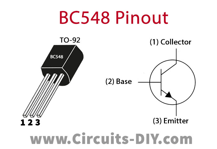
For a detailed description of pinout, dimension features, and specifications download the datasheet of BC548
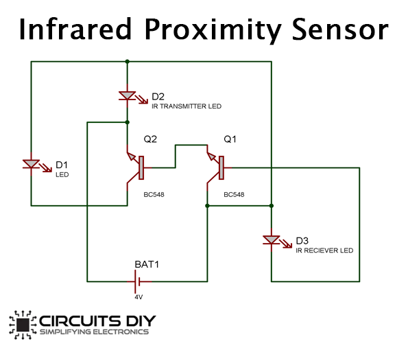
Infrared Proximity Sensor Circuit
Useful Steps
Follow the steps as shown in the video above.
1) Solder the IR transmitter & receiver on the Veroboard.

2) Solder the two BC548 transistors on the Veroboard.
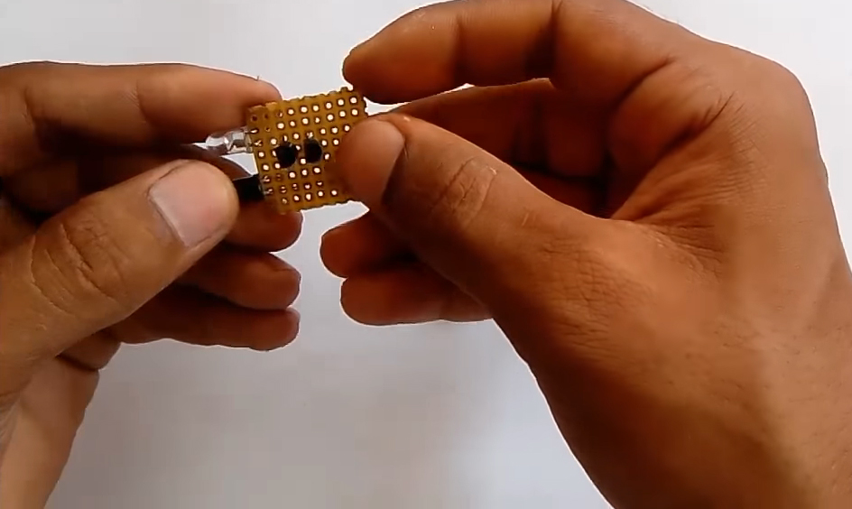
3) Solder the LED on the Veroboard.

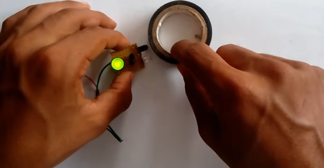
4) Connect DC Battery & power up the circuit.

5) Test the circuit by bringing an arbitrary object near the IR sensor unit.
Working Explanation
the working of this circuit is very simple when any object is brought into the field of vision of an IR transmitter’s radiation. The IR radiation bounces back from the object & is captured by the IR receiver, in order to generate a control signal on the base of transistor Q1, with respect to the intensity of the receiving IR radiation.
The collector output of the Q1 transistor acts as a control signal for transistor Q2, which subsequently triggers the output LED to indicate the presence of an object.
Applications
- It is generally used in small electronic & robotic projects such as LF robots.