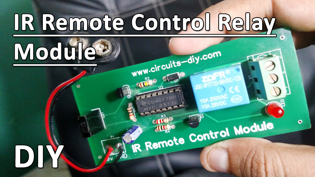
IR (Infrared) Remote Control Switch Circuit is a cost-effective solution for home appliances in our fast-paced life. As a result, much importance has been given to this aspect and a range of remote controls are prevalent today. One of the most frequent is that which makes use of IR radiations at particular frequencies for operations. So In this tutorial, we are going to make an “Infrared IR Remote Control Relay Module” by using TSOP1713 & CD4017 Decade Counter IC.
This circuit is a Remote Operated Home Appliance or Remote controlled Home appliance. The circuit is connected to any of the home appliances (lamp, fan, radio, etc) to make the appliance turn on/off from a TV, VCD, VCR, Air Conditioner, or DVD remote control. The circuit can be activated from up to 8 meters. It is very easy to build and can be assembled on a normal prototype PCB.
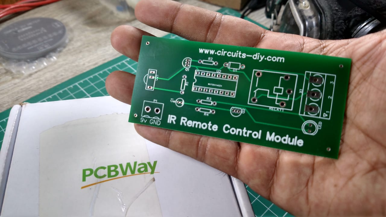
PCBWay commits to meeting the needs of its customers from different industries in terms of quality, delivery, cost-effectiveness, and any other demanding requests. As one of the most experienced PCB manufacturers in China. They pride themselves to be your best business partners as well as good friends in every aspect of your PCB needs.
Hardware Components
The following components are required to make IR Remote Control Circuit
| S. No | Component | Value | Qty |
|---|---|---|---|
| 1. | IC | CD4017 | 1 |
| 2. | Relay | 5v | 1 |
| 3. | IR Remote Control | TSOP1738 | 1 |
| 4. | Transistor | BC547, BC557 | 1 |
| 5. | Battery | 9v | 1 |
| 6. | Diode | 1n4007 | 1 |
| 7. | Resistors | 220, 1k, 10k, 100k | 1 |
| 8. | Electrolytic Capacitor | 1uf | 1 |
| 9. | LED | 1 |
CD4017 Pinout
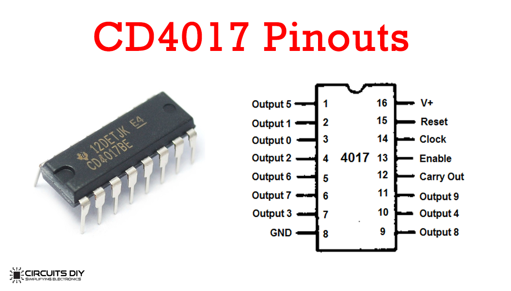
For a detailed description of pinout, dimension features, and specifications download the datasheet of CD4017
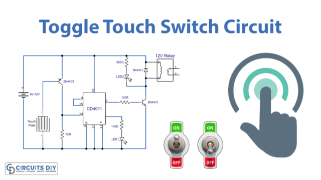
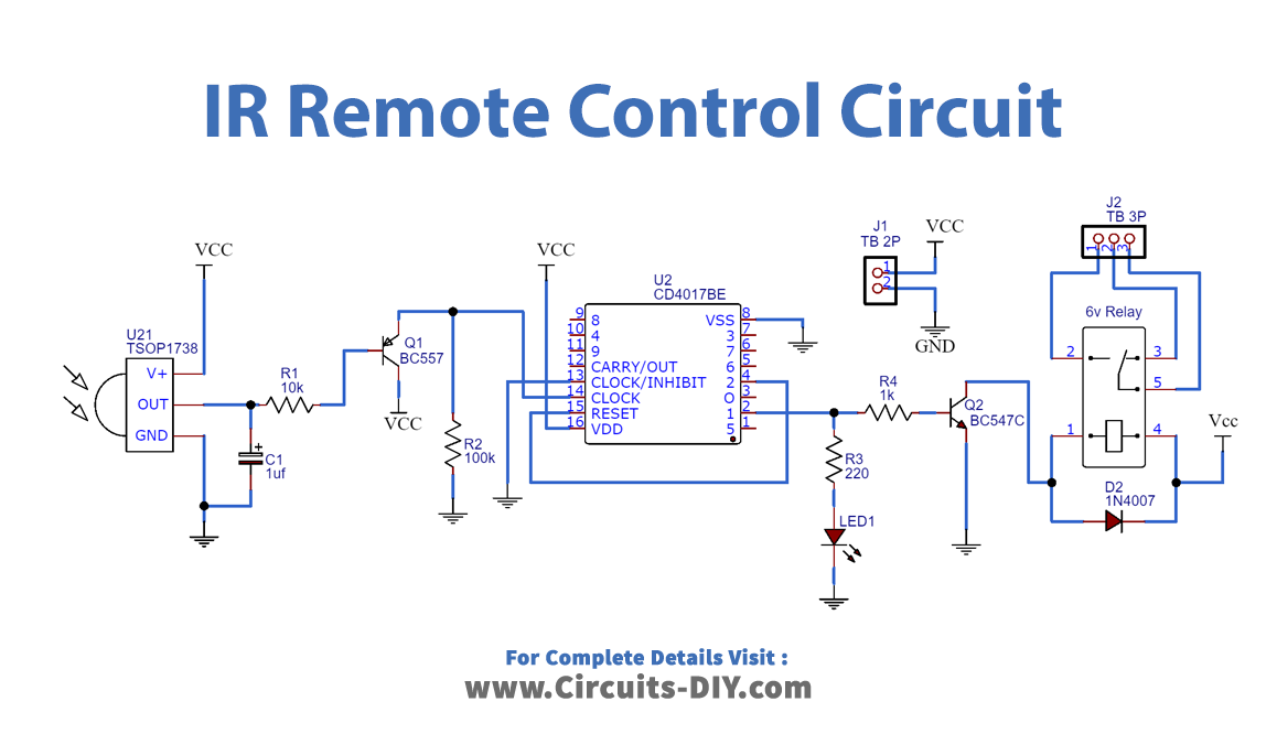
IR Remote Control Circuit
Working Explanation
The 38 kHz IR rays generated by the IR remote control are received by the IR receiver module TSOP 1738 of the circuit. Pin1 of TSOP1738 goes to the ground, pin2 goes to the power supply and the output is available at pin3 through 10k resistor R1. The output signal is amplified by transistor Q1 (BC557). The amplified signal is given to clock pin 14 of decade counter IC CD4017 (IC1). Pin8 of IC goes to the ground supply, pin 16 goes to the Vcc supply.
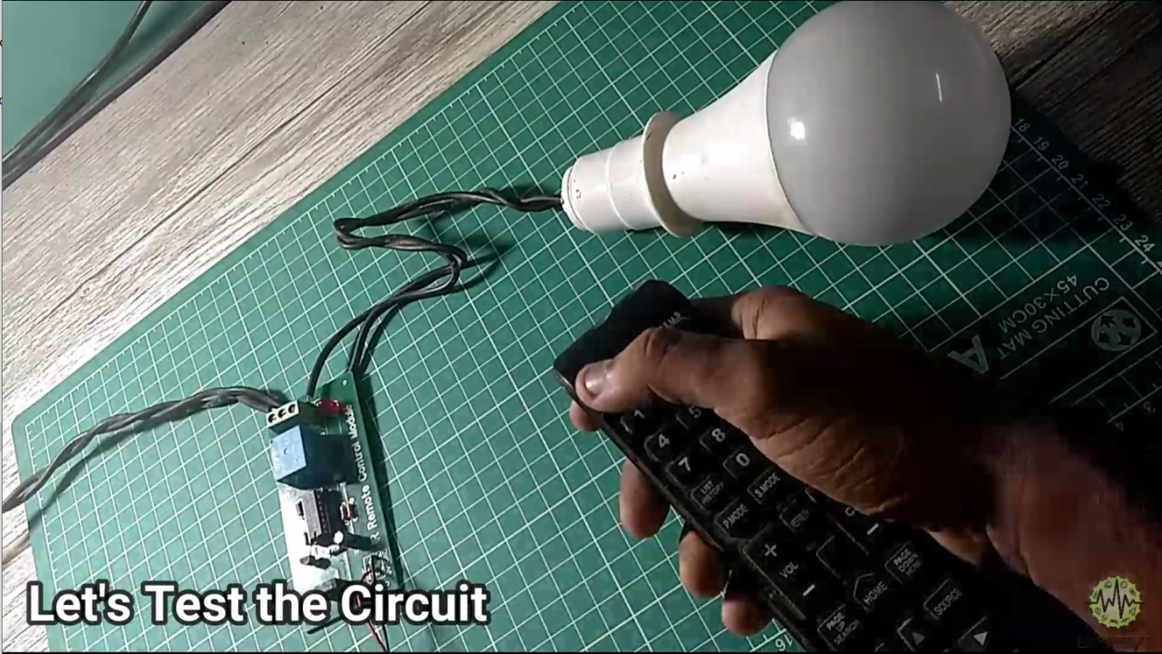
The output of IC1 is taken from its pin2 of IC. A Red LED connected to pin2 is used to indicate the ‘on’ state of the appliance. Transistor Q2 (BC547) base connected to pin2 of IC1 which drives the relay and acts as a switching mechanism. The appliance to be controlled is connected to the pole of the relay and the neutral terminal of the mains. It gets connected to the live terminal of AC mains via normally opened (N/O) contact when the relay gets input. As the result, we get a relay toggling on each press on the remote. Any appliance connected to this circuit can be switched ON or OFF.
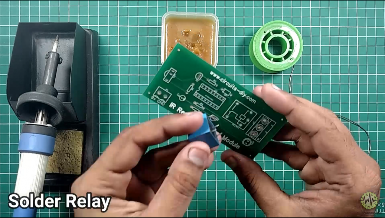
Steps
Solder Relay
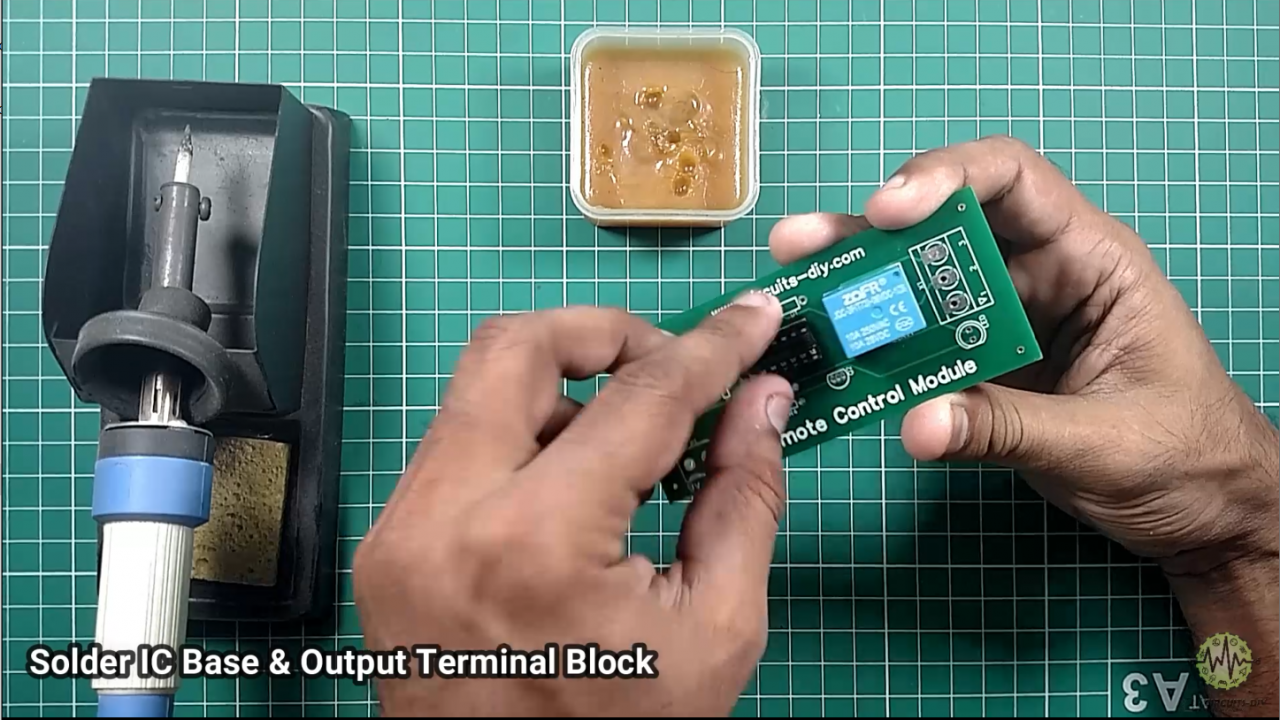
Then Solder IC Base & Output Terminal Block
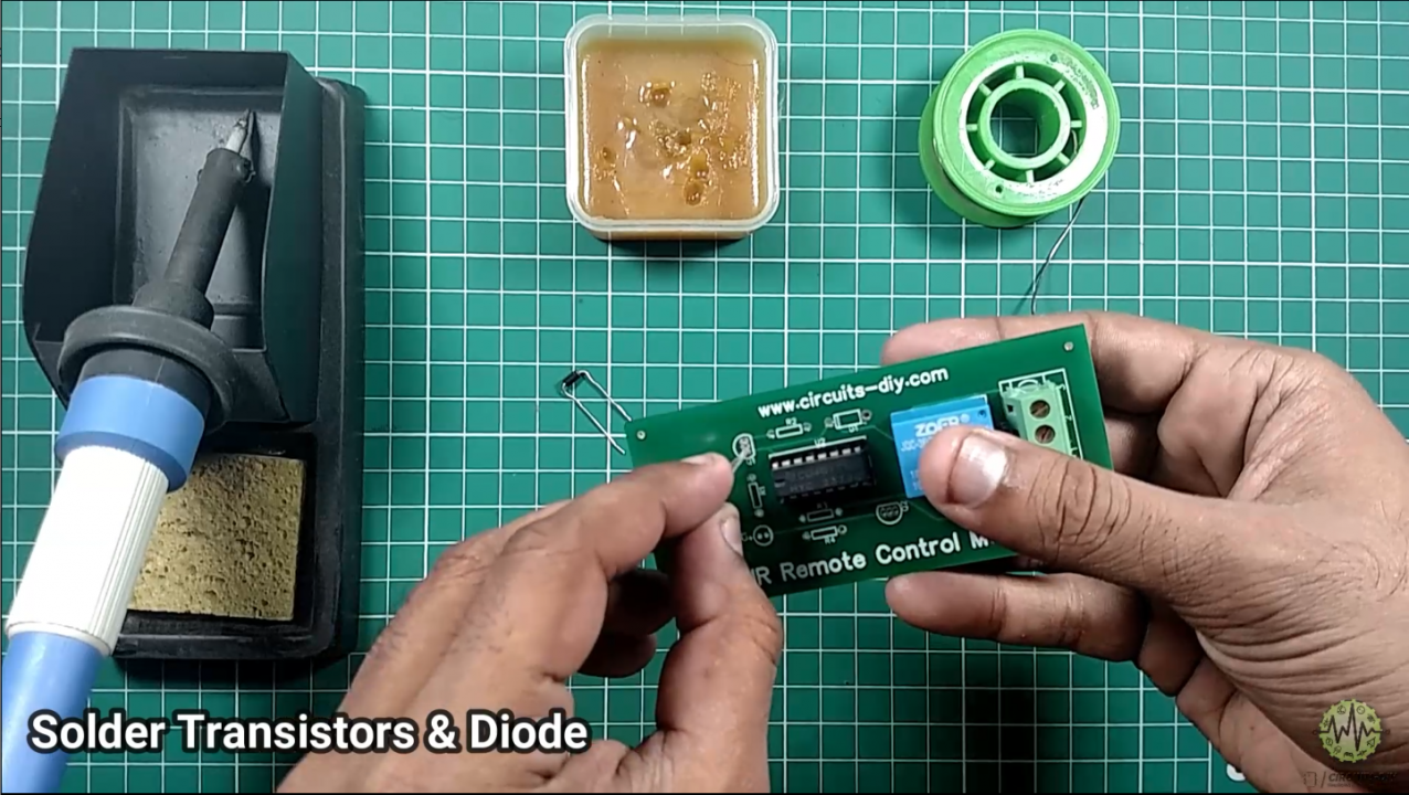
Solder Transistors & Diode
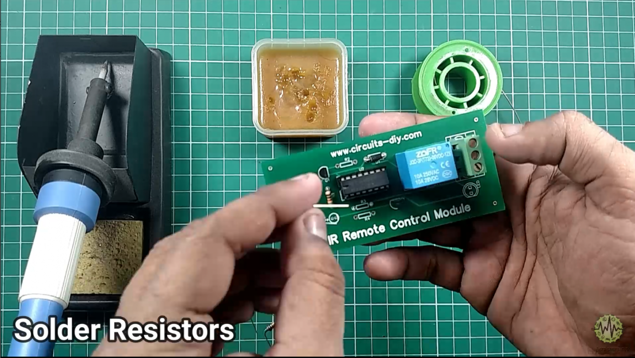
Insert all Resistors and sold it
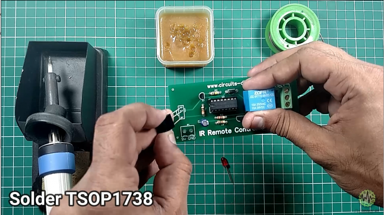
Solder TSOP1738
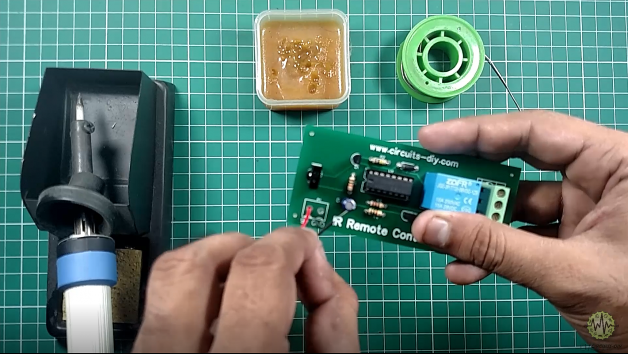
Solder Output Connector
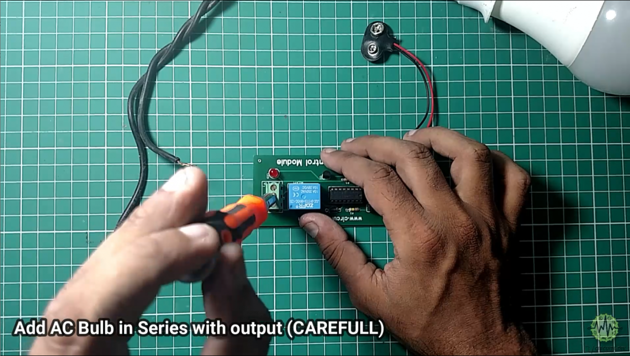
Add AC Bulb in Series with output carefully
Let’s Test the Circuit
Features & Application
- Remotely Control Home Appliances (Fridge, TV, Fan, etc)
- Wireless Controlling
- Long-Distance Communication