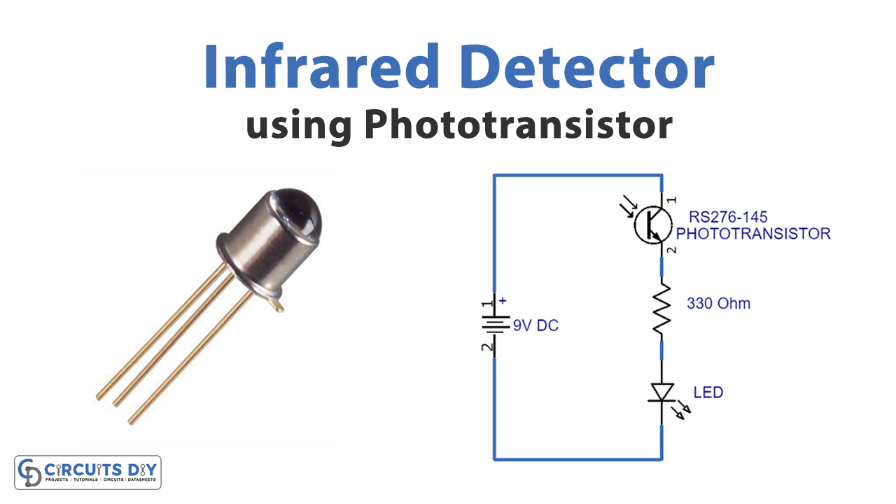
In this tutorial, we are making a very simple project of an Infrared Detector Circuit that detects infrared light. This circuit is using only three components an RS-276-145 phototransistors, 330Ω resistor, and a LED (Light Emitting Diode).
Phototransistors exhibit the operation of both photodiodes and normal transistors. Their base terminal is exposed so instead of sending the current into the base. The photons coming from the striking light activate the transistor. The phototransistor that we are using in our circuit is an IR phototransistor and it detects infrared light. When infrared light strikes the surface of an IR phototransistor it starts conducting across from collector to emitter. This circuit is super easy to build as it is using only three components and a battery, it is an ideal circuit for those who need a DIY IR detector.
Hardware Components
The following components are required to make IR Detector Circuit
| S.no | Component | Value | Qty |
|---|---|---|---|
| 1. | Breadboard | – | 1 |
| 2. | Connecting Wires | – | 1 |
| 3. | Battery | 9v | 1 |
| 4. | LED | 5mm | 1 |
| 5. | Resistor | 300 ohm | 1 |
| 6. | Phototransistor | – | 1 |
IR Detector Circuit

Working Explanation
The operating voltage of this circuit is 9 volts. You can use a battery to power this circuit up. It is a really small circuit that can easily be fitted anywhere with the battery.
When infrared light falls onto the surface of the phototransistor which is made up of infrared light-sensitive material. It responds to this infrared light and conducts. This will give the required voltage to the LED and it lights up. Infrared phototransistors are rated on the wavelengths of the infrared light so they should match up with a phototransistor that detects their specific wavelength.
Applications and Uses
It can be used to detect the presence of IR signals from any electronic source in its vicinity like an IR remote control or infrared burglar alarm system.