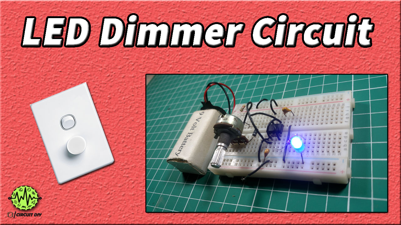
Today in this tutorial I am going to show you step by step how to make a simple LED Dimmer using 555 Timer so let’s start by watching this video. The underlying principle of the LED Dimmer circuit is Pulse Width Modulation (PWM) with the help of the 555 Timer IC. This technique varies the voltage and we can observe the dimming effect on the led.

Hardware Components
The following components are required to make LED Dimmer Circuit
| S. NO | Component | Value | Qty |
|---|---|---|---|
| 1. | Breadboard | – | 1 |
| 2. | Battery | 9v | 1 |
| 3. | Connecting Wires | – | 1 |
| 4. | IC | NE555 Timer | 1 |
| 5. | Resistors | 1k, 220 ohms | 1,1 |
| 6. | Diode | 1N4148 | 2 |
| 7. | Variable Resistor | 10k | 1 |
| 8. | Ceramic Capacitor | 100nF | 2 |
| 9. | LED | 5mm | 1 |
555 IC Pinout

For a detailed description of pinout, dimension features, and specifications download the datasheet of 555 Timer
Circuit Diagram
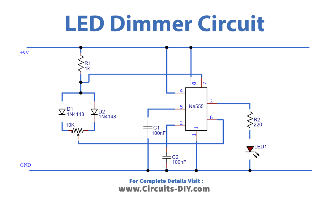
Working Explanation
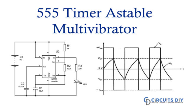
Pulse Width Modulation (PWM) is an important term for regulating the input and output of the circuits. In LED Dimmer Circuit, we are using this technique to provide a dimming effect on the LED. The 555 timer IC has three modes of operation Bistable, Astable, and Monostable. Controlling the feature of this IC like timing from a few seconds to several seconds and setting the duty cycle with a combination of resistor and capacitor are helpful for the diming of LED. By varying, the amount of power delivered to the circuit and regulating the pulse width of the signal intensity of Led is controlled.


