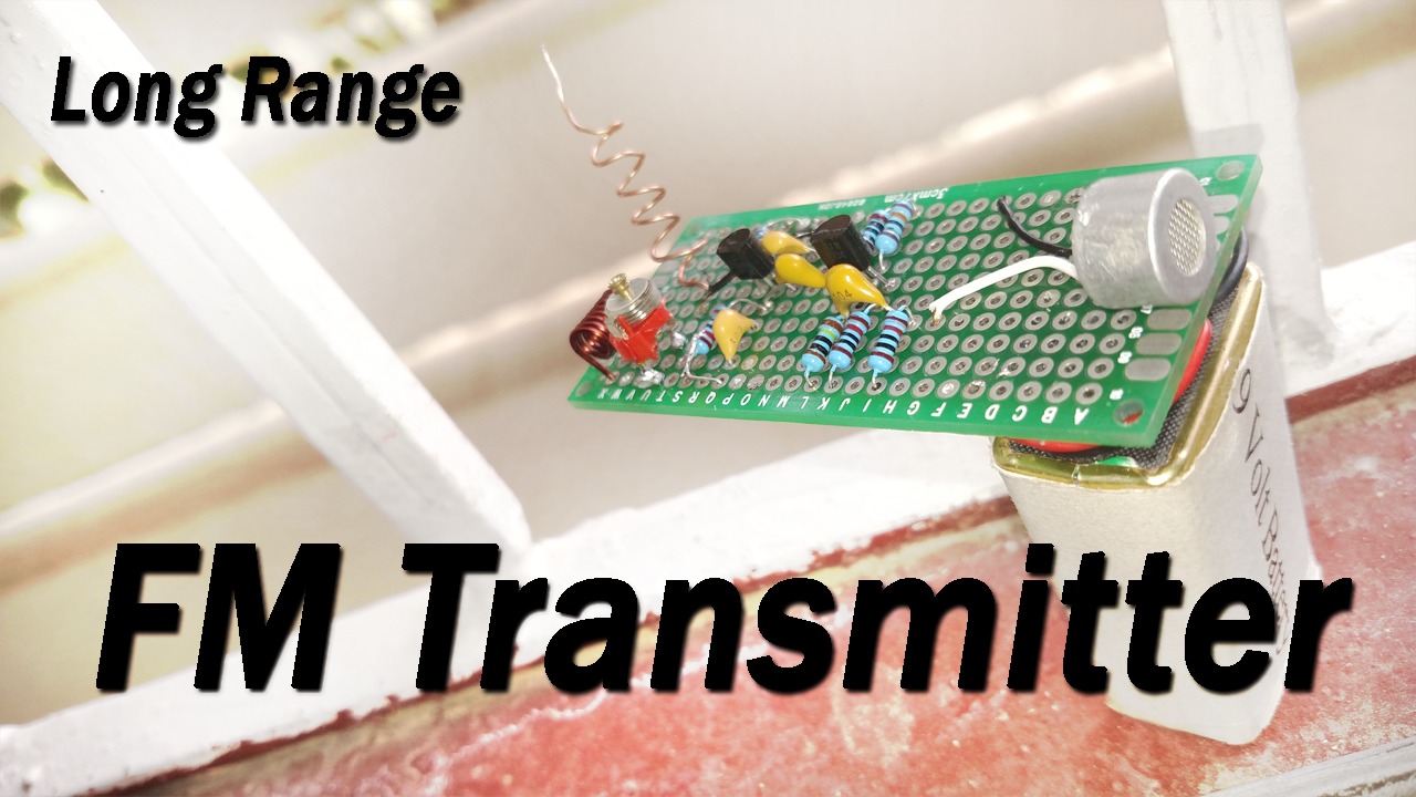
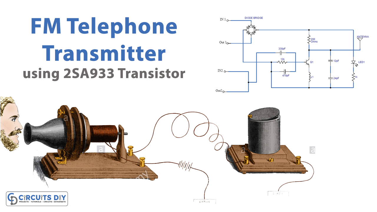
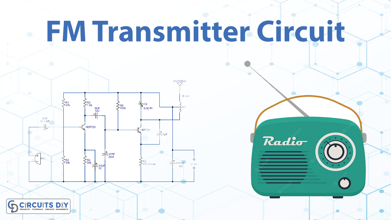
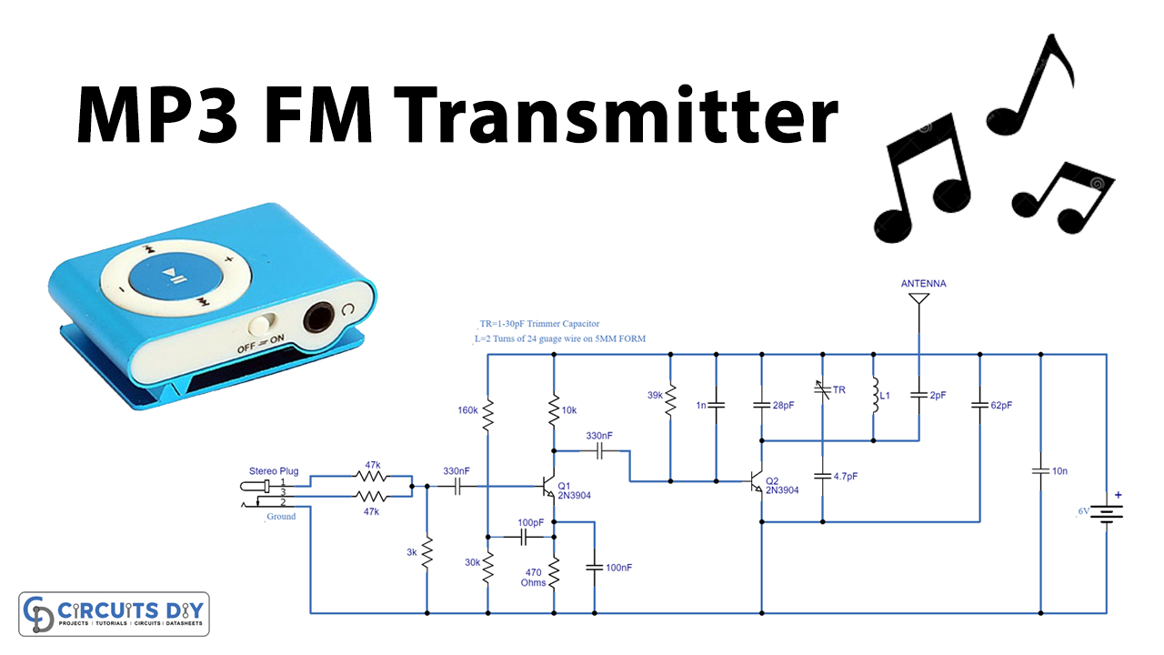
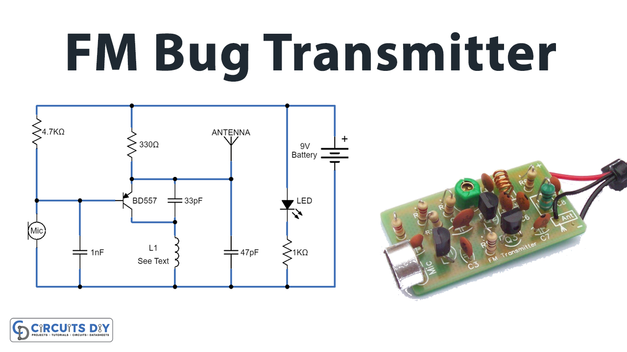
FM Transmitter circuit is one of the cool projects to build with a good range. The FM transmitter we are going to make is long-range although you can increase more range with the help of a large antenna.
An FM transmitter is a gadget that uses the standards of frequency modulation to broadcast sound provided at its input.
Typical FM transmitter design’s normally comply with the block graph below

Hardware Components
The following components are required to make FM Transmitter Circuit
| S. No | Components | Value | Qty |
|---|---|---|---|
| 1. | Vero PCB Board | – | 1 |
| 2. | NPN Transistor | 2N3904 | 2 |
| 3. | Variable Capacitor | (4-40pf) | 1 |
| 4. | Ceramic Capacitor | 0.1uF, 0.01uF, 4.7pF | 2, 1, 1 |
| 5. | Inductor | 0.1uH | 1 |
| 6. | Resistors | 100K, 10K, 1M, 100 ohm | 1, 3, 1, 1 |
| 7. | Condenser Mic | – | 1 |
| 8. | 9V Battery | – | 1 |
2N3904 Pinout

For a detailed description of pinout, dimension features, and specifications download the datasheet of 2n3904
FM Transmitter Circuit

Working Explanation

The sign energy of audio inputs into the transmitter is typically low therefore an amplifier is typically constructed to deliver the signal level up. Based on the preferred frequency for transmission (which is normally between the FM frequency band, 88MHz to 108MHz), the service frequency is generated using an oscillator circuit and blended with an A
Application
- The FM transmitters are used in the homes like sound systems in halls to fill the sound with the audio source.
- These are also used in cars and fitness centers.
- The correctional facilities have used FM transmitters to reduce the prison noise in common areas.

