
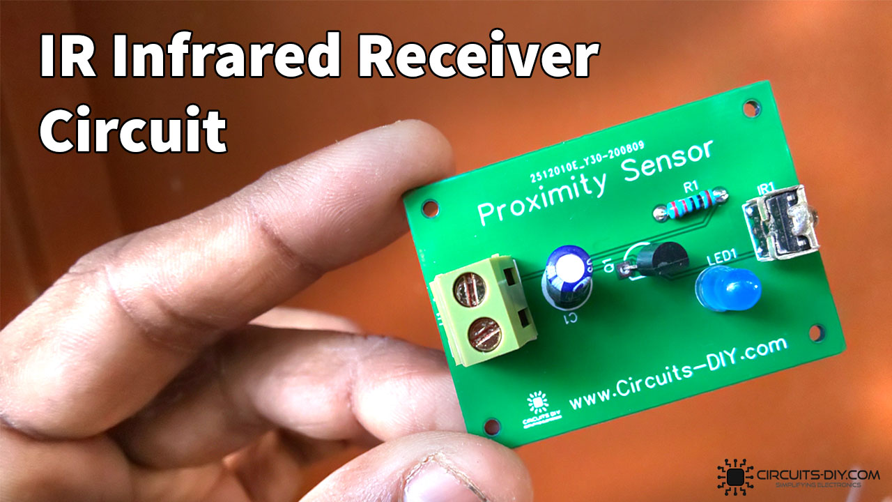
An IR receiver or photodiode is a simple electronic circuit that collects IR rays transmitter from a source such as a TV remote or an LED that can emit IR rays and transduces it into an electrical signal which can, later on, be used to control any device such as home appliances or lighting fixtures, etc.
The use of IR technology has seen a tremendous uprise in the current industry with applications ranging from touchless switches to complex industrial CNCs. So, In today’s tutorial, we are going to cover a step-by-step process on how to design How to make IR Infrared Reciever Module Using VS1838B IR Sensor.
VS1838B IR Receiver LED
VS1838B is a high-quality infrared sensor that operates at a 38kHz frequency. It is a miniaturized infrared receiver for remote control and other applications requiring improved ambient light rejection. This module has excellent performance even in disturbed ambient light applications and provides protection against uncontrolled output pulses. It comprises a PIN diode, a preamplifier, and other signal conditioning circuitry integrated into the package. This makes the device easily interfaced with a Microcontroller.
JLCPCB is the foremost PCB prototype & manufacturing company in china, providing us with the best service we have ever experienced regarding (Quality, Price Service & Time).
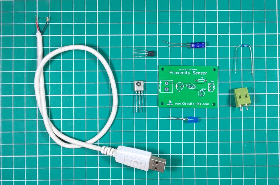
Hardware Components
The following components are required to make IR Infrared Reciever Circuit
| S.no | Component | Value | Qty |
|---|---|---|---|
| 1. | IR Receiver PCB | – | 1 |
| 2. | Transistor | BC547 | 1 |
| 3. | IR Receiver | VS1838B | 1 |
| 4. | Resistor | 150 | 1 |
| 5. | Electrolytic Capacitor | 47uf | 1 |
| 6. | 2-pin Terminal Block | – | 1 |
| 7. | USB Cable | 5v | 1 |
| 8. | LED |
VS1838B Pinout
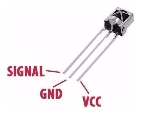
For a detailed description of pinout, dimension features, and specifications download the datasheet of VS1838B
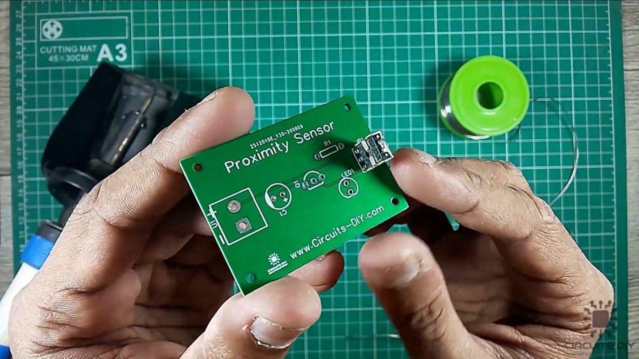
IR Infrared Reciever Circuit

Useful Steps
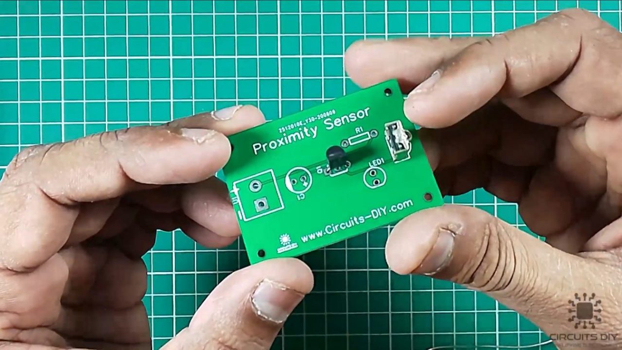
1) Solder the VS1838B IR receiver on the Veroboard.
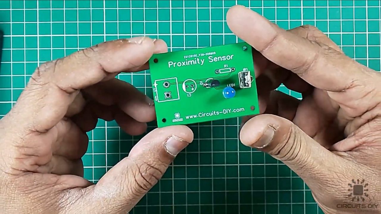
2) Solder the BC547 transistor on the Veroboard.
3) After that, solder the LED on the Veroboard.
4) After that, solder the 47uF capacitor on the Veroboard.
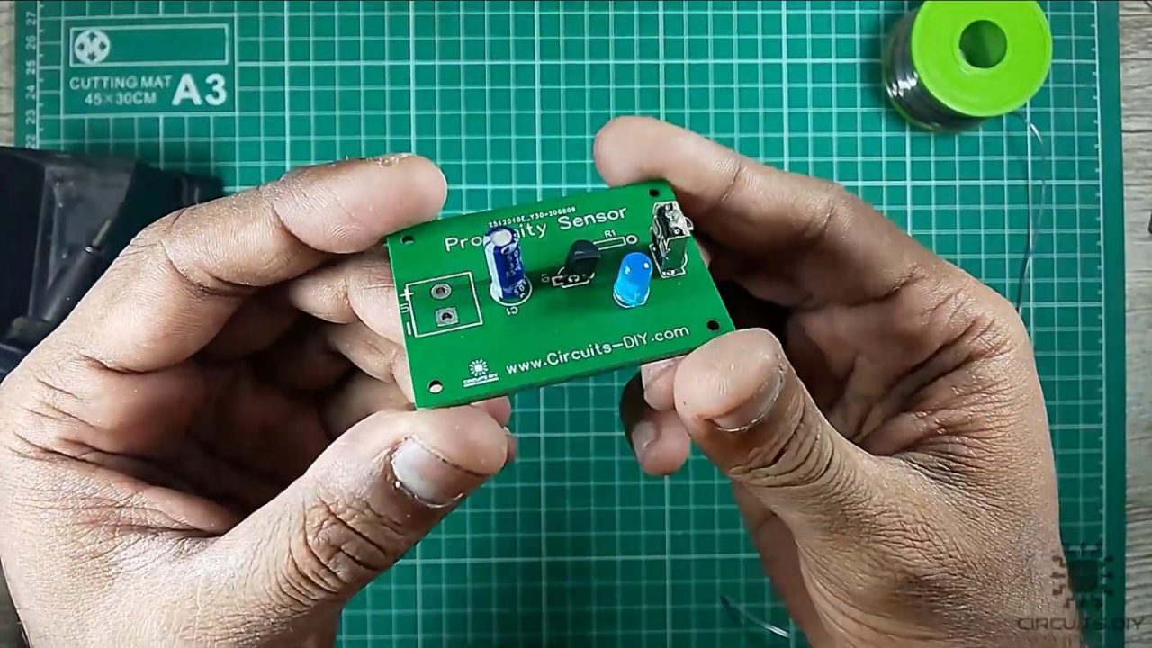
5) After that, solder the 470 Ohm resistor and the output block connector on the Veroboard.
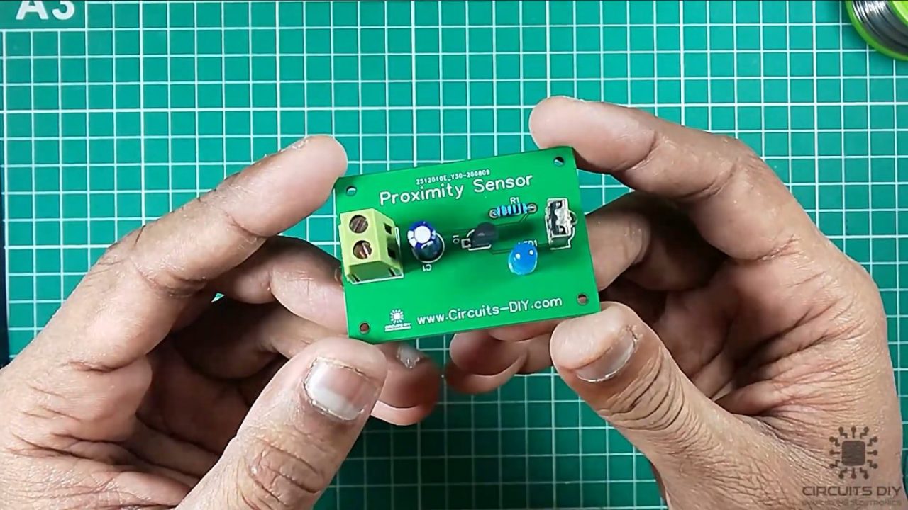
6) Power up and test the circuit using a 5V DC supply.
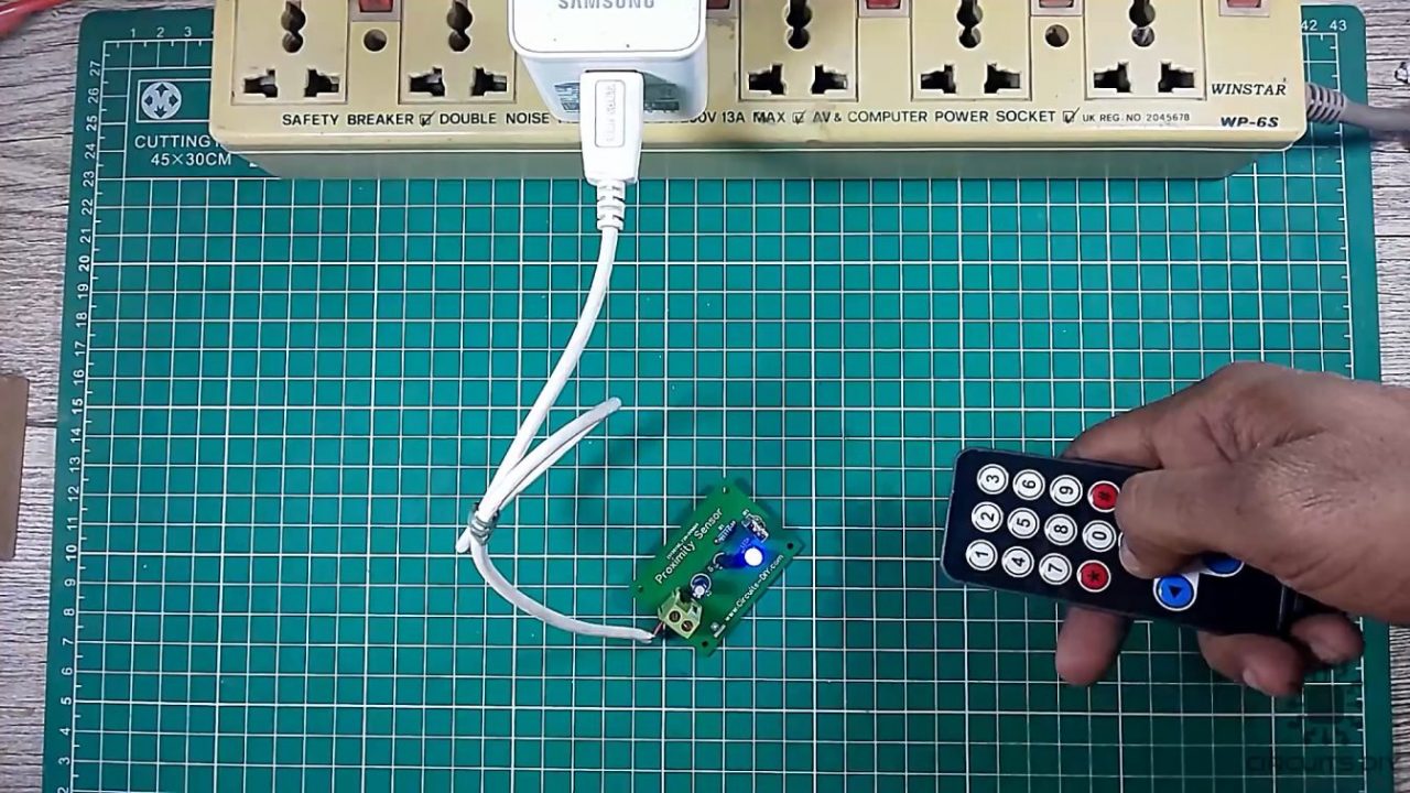
Working Explanation
The working of this circuit is as follows. When an IR ray is transmitted by a device such as an IR LED or TV remote, The IR receiver collects the IR rays and generates an output at the Q pin of the receiver. The output from the receiver then acts as a control signal on the base of the BC547 transistor.
The collector output from the transistor then goes on triggering the LED or any other device connected to the BC547 collector terminal. You can use a 5V – 9V battery to power this circuit.
Applications
- Used as an Optical switch
- AV instruments such as Audio, TV, VCR, CD, MD, DVD, etc.
- Home appliances such as air-conditioners, fans, etc.
- CATV set-top boxes
Related posts:
 How to make a Simple Heartbeat Sensor Circuit
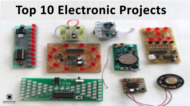 Top 10 Simple Electronics Projects For Complete Beginners
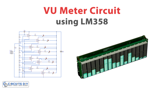 Simple VU Meter Circuit using LM358 - Electronics Projects
 How to make 12 Volt 3 Ampere Power Supply - DIY
 How To Make Multi-Color RGB LED Light At Home - DIY
 How To Make A Touchless Hand Sanitizer Dispenser - DIY Project


1 thought on “How to make IR Infrared Reciever Module Using VS1838B IR sensor”
Comments are closed.