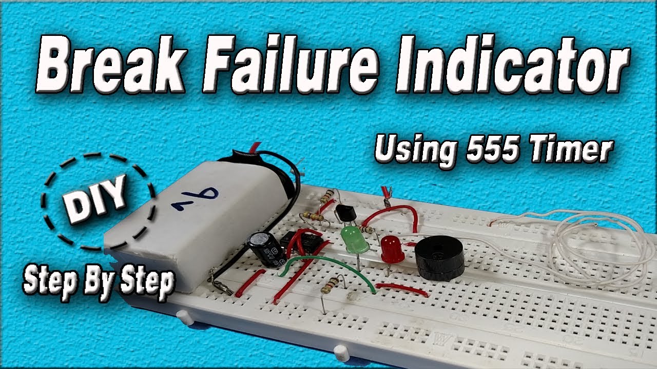
A brake Failure Indicator is always an important need i.e. break wire does not break by letting you know I am going to break! So in many cases, we need some indication to slow down our vehicles to avoid accidents. In this project, we are going to make a Brake Failure Indication Circuit using a 555 Timer IC that can be attached to our Vehicles. It constantly monitors the status of the wire and gives an alarming sound when the wire breaks. Watch the video for Step-by-step instructions
The heart of this circuit is a NE555 Timer IC. The IC possesses an oscillation frequency ranging from 670 to 680 Hz. Here, this NE555 timer acts as an Astable multi-vibrator. An A-stable multi-vibrator is a free-running oscillator that switches continuously between its two unstable states. With no external signal applied, the transistors alternately switch from cutoff to saturation state at a frequency that RC time constants of the coupling circuit determine. If these time constants are equal (R and C are equal) then a square wave will generate with a frequency of 1/1.4 RxC. Hence, an Astable multivibrator is also a pulse generator or a square wave generator.

Hardware Components
The following components are required to make a Brake Failure Indicator Circuit.
| S. No | Component | Value | Qty |
|---|---|---|---|
| 1 | Breadboard | 1 | |
| 2 | IC | NE555 Timer | 1 |
| 3 | PNP Transistor | BC557 | 1 |
| 4 | LED | 2 | |
| 5 | Electrolytic Capacitor | 1uF | 1 |
| 6 | Ceramic Capacitor | 0.1uF | 1 |
| 7 | Resistors | 1K, 440K | 2, 1 |
| 8 | Buzzer | 1 |
555 Timer Pinout

For a detailed description of pinout, dimension features, and specifications download the datasheet of 555 Timer IC
Brake Failure Indicator Circuit
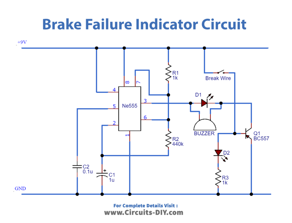
Working Explanation
On powering the circuit, make sure the Brake cable is connected across the +5V and base of BC557 through a resistor with respect to the circuit diagram in order to ensure proper functioning.
In standard operating conditions, you should see the Green LED turn on and the Buzzer and Red Light Turn Off. Now, removing or cutting the brake cable should trigger the Red LED and the Buzzer and they should start flashing, reflecting proper functioning.
Applications
- Commonly serves as a fail-safe mechanism in vehicles such as Cars, Buses & Bikes.


