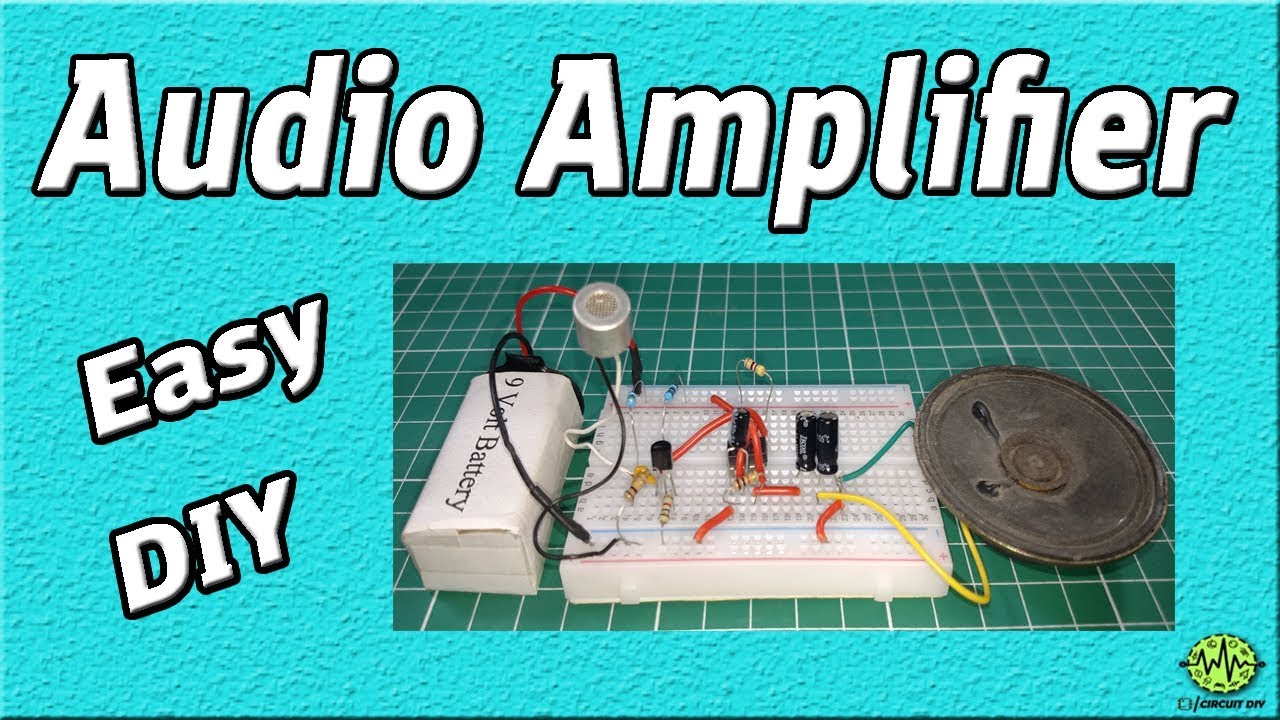
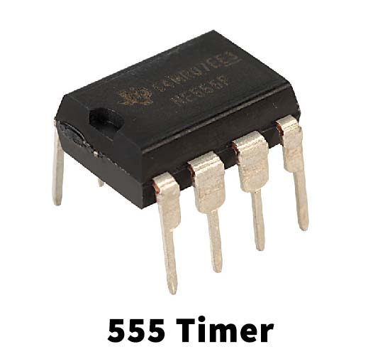
555 time IC is a very powerful and versatile IC, it can be used in many modes like Astable, Bistable, and Monostable. So in this tutorial, we are going to make an “Audio Amplifier Circuit using 555 Timer“. A low-power audio signal can be amplified using a 555 Timer IC.
This circuit is divided into two parts one is the Preamplifier circuit, which consists of a BC547 transistor, and the second part consists of an 8-ohm speaker and a 555 timer IC, which is oscillating in Astable multivibrator mode, with approx. 66KHz frequency. An astable multivibrator is a free-running oscillator that switches continuously between its two unstable states. With no external signal applied, the transistors alternately switch from cutoff to saturation state at a frequency that RC time constants of the coupling circuit determine. If these time constants are equal (R and C are equal) then a square wave will generate with a frequency of 1/1.4 RxC. Hence, an astable multivibrator is also a pulse generator or a square wave generator.
Hardware Components
The following components are required to make Audio Amplifier Circuit.
| S.No | Components | Value | Qty |
|---|---|---|---|
| 1 | IC | NE555 Timer | 1 |
| 2 | Transistor | BC547 | 1 |
| 3 | Buzzer | 1 | |
| 4 | Condenser Mic | 1 | |
| 5 | Electrolytic Capacitor | 1nf, 10uf | 2,2 |
| 6 | Resistor | 1k,10k,100k,470,47k,680k | 1 |
| 7 | Ceramic Capacitor | 1nf, 10uf | 1,2 |
555 Timer Pinout

For a detailed description of pinout, dimension, features, and specifications download the datasheet of 555 Timer
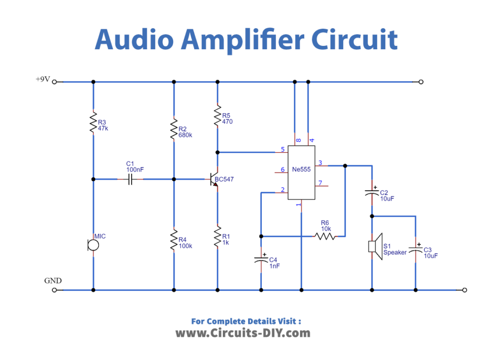
Audio Amplifier Circuit
Working Explanation
The heart of this circuit is a NE555 timer IC. Audio amplifiers are generally used to address a large group or audience. There are 2 stages to the operation of this circuit. The Preamp stage & the Amplifier stage. In the first stage, the audio input comes from the electret microphone. Here, a Capacitor (100nF) blocks the DC component, allowing the AC component to flow to the base of the transistor amplifier(BC547). The transistor amplifies the weak AC audio signal and sends it to the Pin 5 (CONT) of the timer IC.
Now in the 2nd stage, the NE555 IC receives the input signal from the preamp stage. It further amplifies the audio signal and sends it to an audio transducer such as a loudspeaker. Resistor R3 is used for biasing of electret Mic and R2 and R4 are used for providing proper biasing to the transistor.
Applications
- Used in audio automotive designs such as car stereos, radios & Hi-Fi audio setups.
- Widely used in sound systems such as speakers, high-power megaphones, & large-scale acoustic systems.