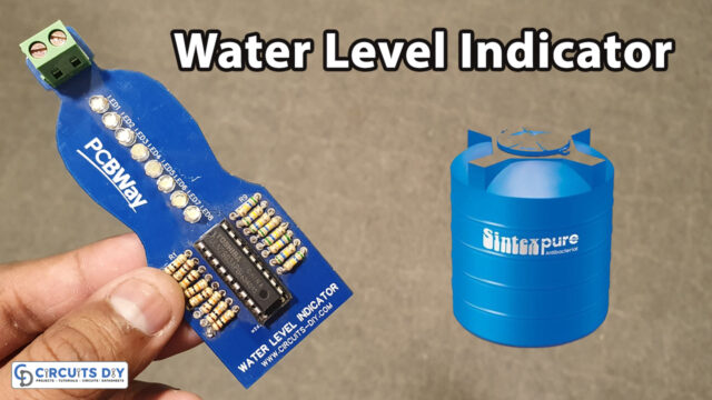
The water level indicator is characterized as a system or apparatus which gets the data about the water level in containers or in tanks. By deploying the water level indicator we can control the overflow of water from the reservoir.
In this DIY tutorial, we will demonstrate how to design a Water Level Indicator with the help of a 7-segment digital display. Most of the water level indicator apparatuses depend on the number of LEDs that gleams to a specific number to demonstrate the approximate level of water in the compartment.
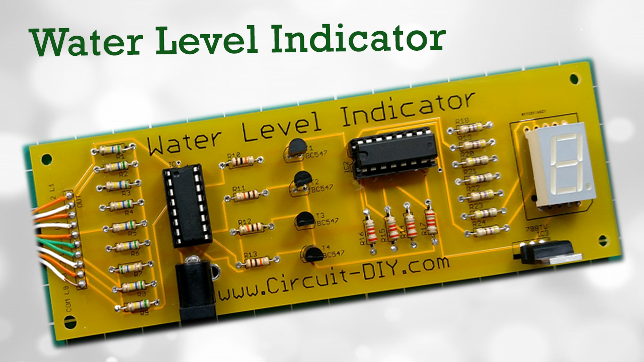
Here we have designed and fabricated a Numeric Water Level Indicator utilizing IC 74147 and CD4511. It is a ‘Digital Version’ of the water level indicator apparatus utilizing a 7-segment display to show the water level in numeric structure from 0 to 9 digits.
Hardware Components
The following components are required to make Water Level Indicator Circuit
| S.no | Component | Value | Qty |
|---|---|---|---|
| 1. | Breadboard | – | 1 |
| 2. | Battery | 9V | 1 |
| 3. | Connecting wires | – | 1 |
| 4. | PCB Water Level Indicator | – | 1 |
| 5. | IC | 74HC147 | 1 |
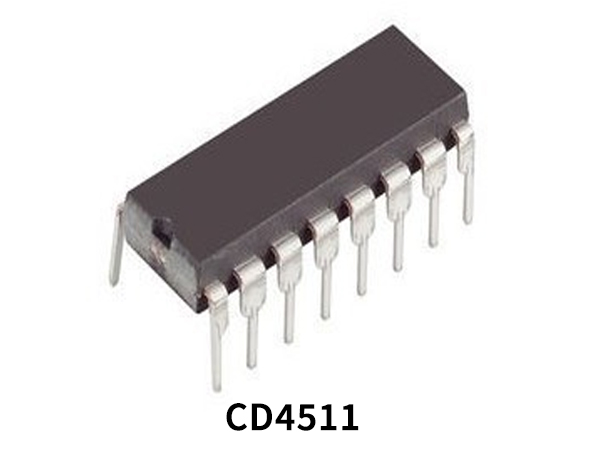
| 6. | IC | CD4511 | 1 |
| 7. | DC Power Jack | – | 1 |
| 8. | 7 Segment Common Cathode | – | 1 |
| 9. | NPN Transistors | BC547 | 4 |
| 10. | Resistors | 560k, 3.3k, 12k, 470ohm | 9, 4, 4, 7 |
CD4511 Pinout
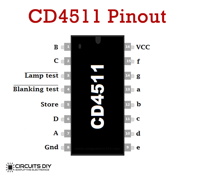
For a detailed description of pinout, dimension features, and specifications download the datasheet of CD4511
74HC147 Pinout
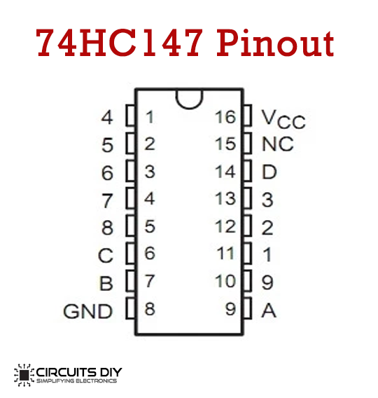
For a detailed description of pinout, dimension features, and specifications download the datasheet of 74HC147
Water Level Indicator Circuit

Useful Steps
Solder 7 Segment common cathode

Solder 470 Ohm resistors

Solder 5v Regulator

Solder CD5411 IC base

Solder BC547 Transistors

Solder 10k Resistors

Solder wire to all levels
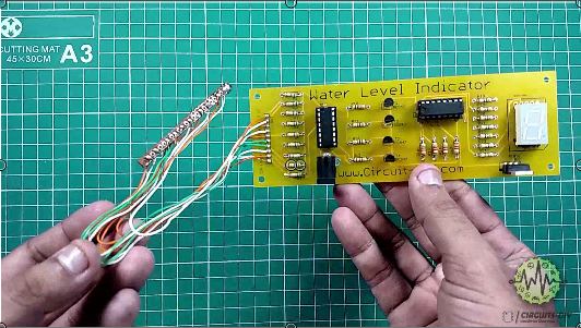
Working Explanation
This circuit is the advanced variant of the water-level indicator. It used a 7-segment LED display to show the water level in numeric structure from “0” to “9”. IC 74147 (IC1), IC CD4511 (IC2), and 7-segment LED Display LTS543 (DIS1) are the main components of the water level indicator. Because of high input impedance, IC1 senses water in the water holder from its nine input terminals.
IC 74174 has nine dynamic low input sources and changes over the dynamic contribution to dynamic low BCD yield output. The input L-9 has the most elevated need. The yield outputs of IC1 (A, B, C, and D) are taken care of by IC2 by means of transistors T1 through T4. This logical inverter is utilized to change over the dynamic low yield output of IC1 into dynamic high for IC2.
At the point when the water tank is in empty condition, all the input of IC1 stays high. Accordingly, its yield output likewise stays high, making all the inputs of IC2 low. Display LTS543 at this stage shows “0”, which implies the water tank is in vacant condition. Also, when the level of the water arrives at the L-1 position, the 7-segment shows “1”, and when the level of the water arrives at the L-2 position, the displa7-segment shows “2”. At last, when the tank is full, all the inputs of IC1 become low and its yield output goes low to make all the contributions of IC2 high. Display LTS543 now shows “9”, which implies the water tank is in full condition.
Application
The applications of the water level indicator are:
- Utilized in water tanks to control water levels
- Sewage pump level control
- Life station switches
- Oil tank level control
- Pool water level control
- Automatically, turn ON/OFF pumps
- Remote observing fluid
- Fuel tank level checking
- Leachate level control
- Water system control
- Cooling tower water level control
- Pump controller
- Water level control


