What is a Timer Switch?
A timer switch is basically a control device that provides an output signal with respect to the input signal provided. It is generally used in commercial or industrial-grade equipment such as HVAC (heating, ventilation, air conditioning) equipment, traffic lighting, and large pumps.
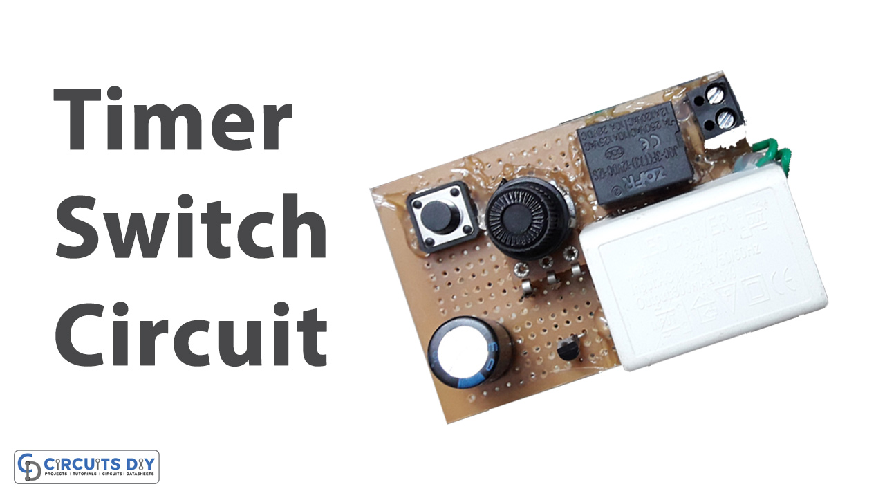
So in this tutorial, we will go through a step-by-step procedure on How to make a Timer Switch using a single BC547 transistor & a small no. of other components.
Hardware Components
The following components are required to make Timer Switch Circuit
| S.no | Component | Value | Qty |
|---|---|---|---|
| 1. | Relay | SPDT/5V | 1 |
| 2. | AC – DC Converter | 220V/12V | 1 |
| 3. | Transistor | BC547 | 1 |
| 3. | Block Connector | – | 1 |
| 4. | Potentiometer | 100K | 1 |
| 5. | Pushbutton | – | 1 |
| 6. | Capacitor | 1000uF | 1 |
| 7. | Diode | 1N4007 | 1 |
| 8. | Wall outlet with Plug | 220V | 1 |
| 9. | Soldering Iron | 45W – 65W | 1 |
| 10. | Soldering Wire with Flux | – | 1 |
| 11. | Veroboard | – | 1 |
| 12. | Jumper wires | – | As per need |
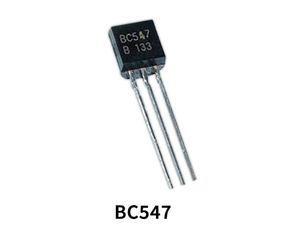
BC547 Pinout
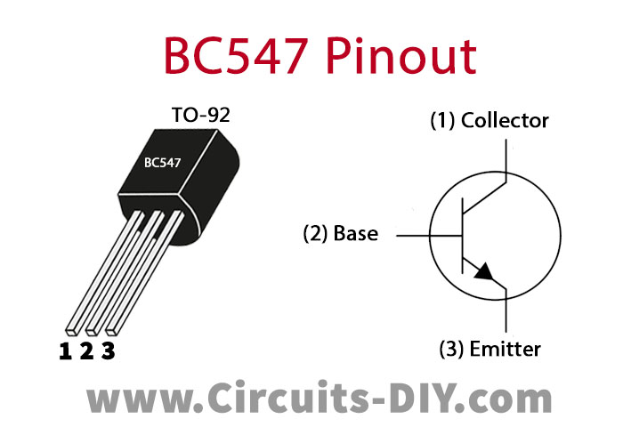
For a detailed description of pinout, dimension features, and specifications download the datasheet of BC547
Useful Steps
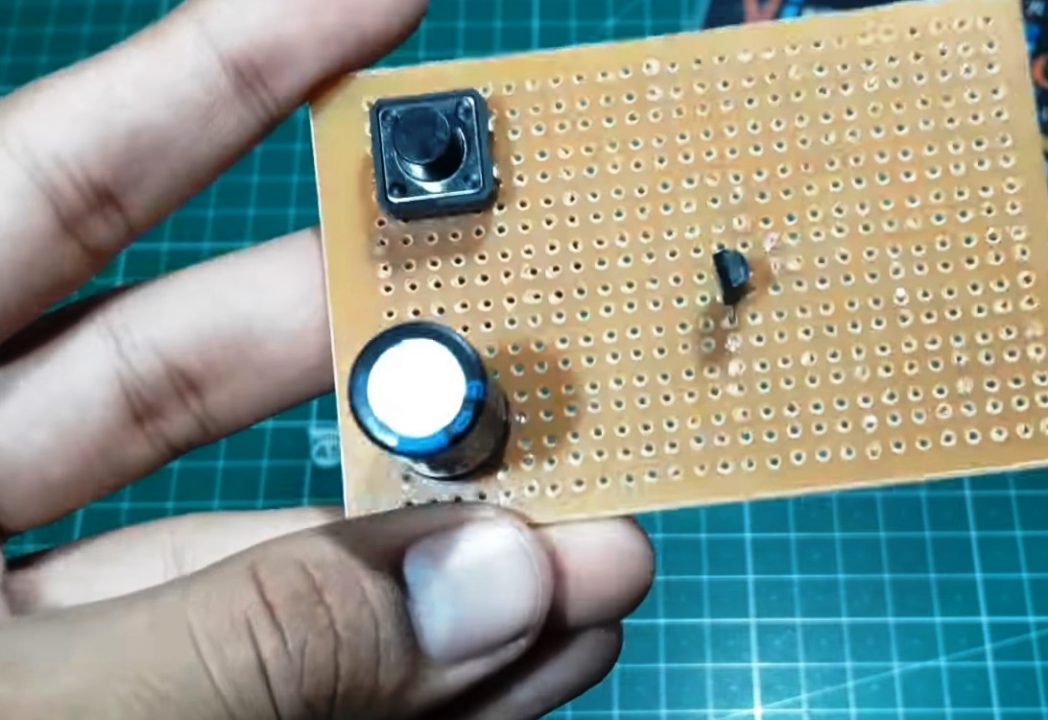
1) Solder the 1000uF capacitor & the pushbutton on the Veroboard.

2) After that, solder the BC547 transistor on the Veroboard. Also, solder the +ve terminal of the capacitor with the pushbutton & the -ve terminal with the emitter of the transistor.
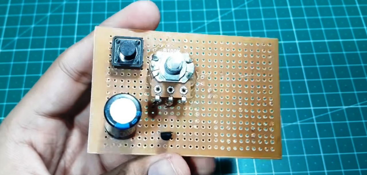
3) Solder the potentiometer between the +ve terminal of the capacitor & the base of the transistor.
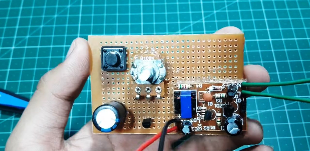
4) Solder the AC to DC converter on the Veroboard.
5) Solder the relay & output block connector on the Veroboard.
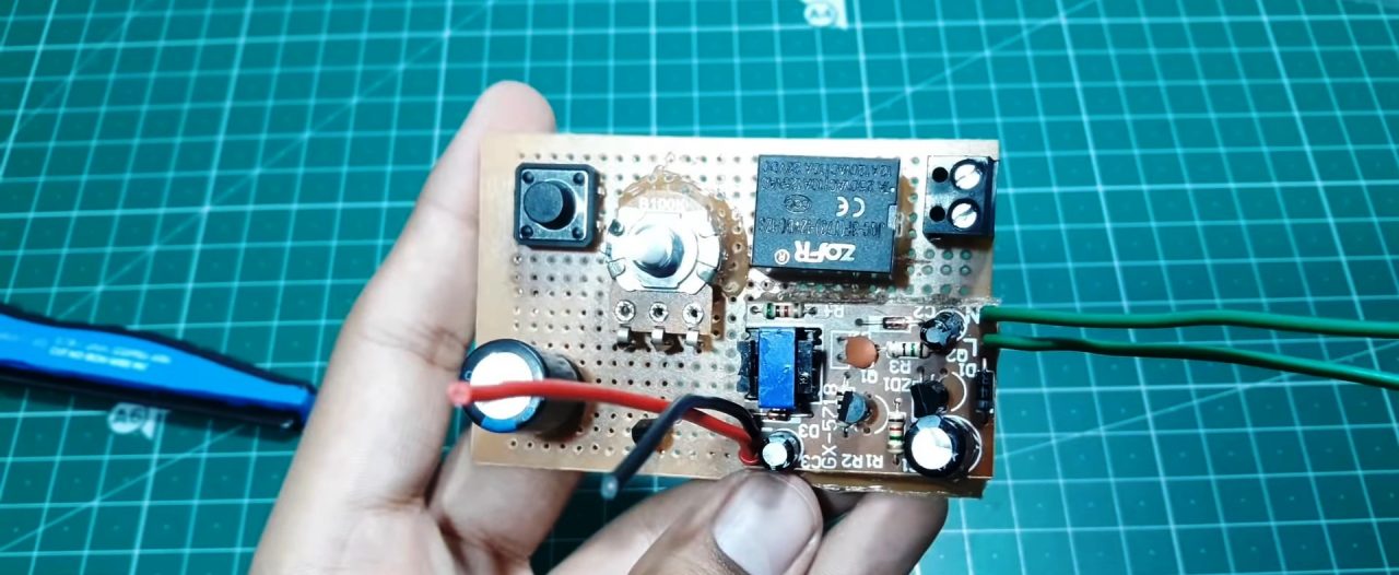
6) Set the preset time by tuning the Pot. After that, Power-up & tests the circuit.
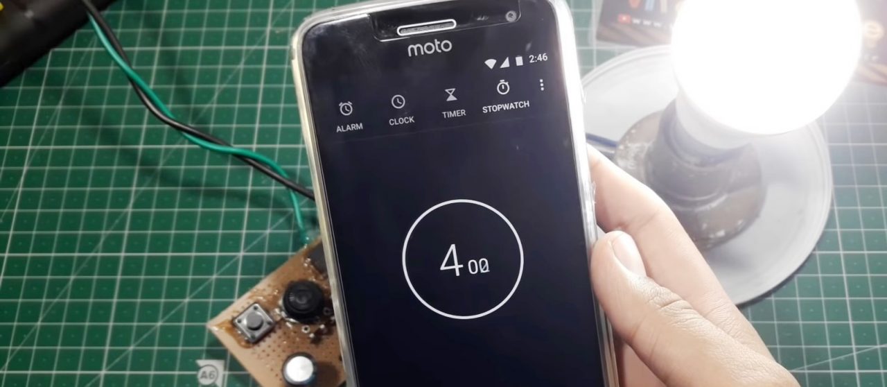
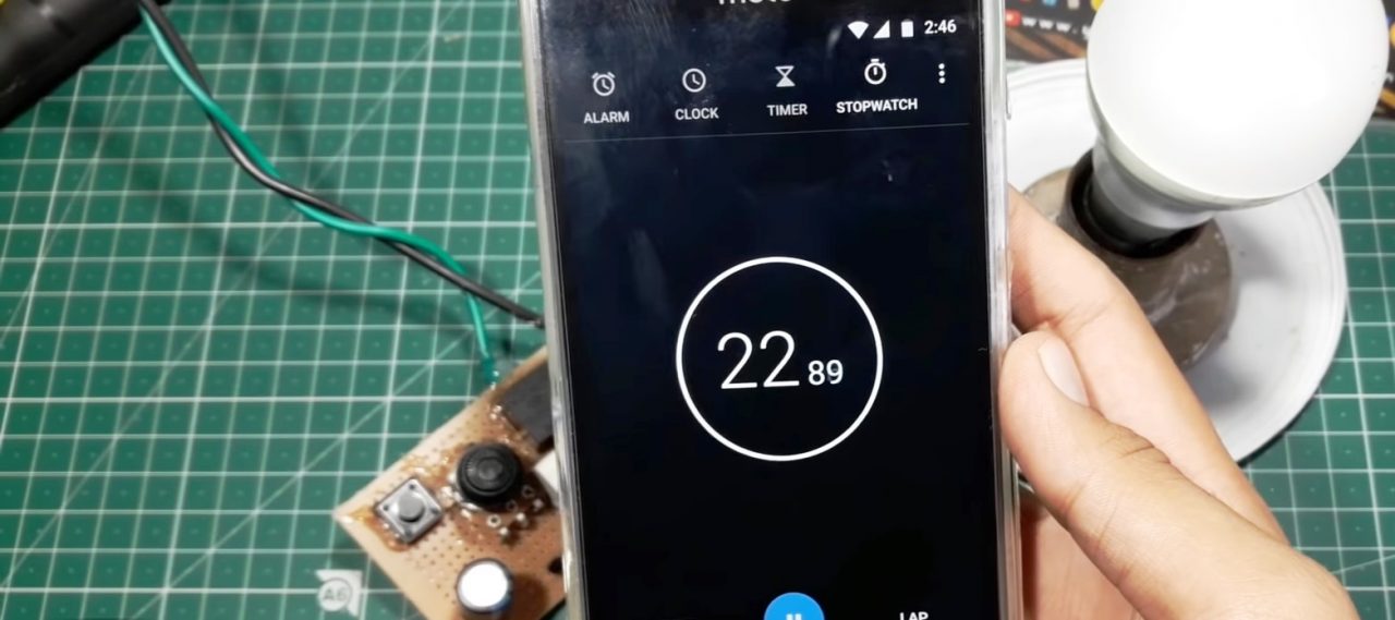
Working Explanation
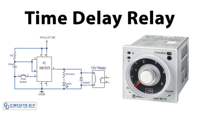
The working of this circuit is pretty simple. The 100K potentiometer sets the preset of the circuit on powering. On pressing the pushbutton, the 1000uF capacitor gets charged & discharges as per the delay introduced by the preset pot.
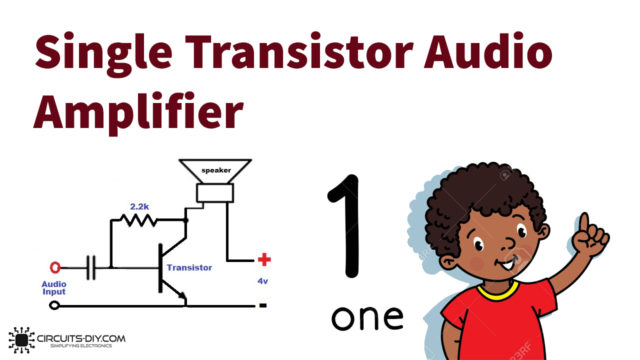
The capacitor output acts as a control signal to the base of the BC547 transistor. The collector output energizes the coil of the 5V SPDT relay with a diode connected in parallel as a -ve feedback protection scheme. This makes the relay switch & switches ON the external circuit connected between the COM & NC/NO terminal. The 220V AC to 12V DC converter acts as the supply for both the timer switch & the external circuit attached to the relay. Always use an SPDT relay with a voltage rating comparable to the input power supply (12V/9V/5V).
Applications
- They generally serve as a stabilizing protection scheme for surge-sensitive appliances such as UPS, Fridge, Air Conditioners & Deep Freezers.
- Also used in devices such as Power banks, Stopwatches, Coffee makers, etc.


