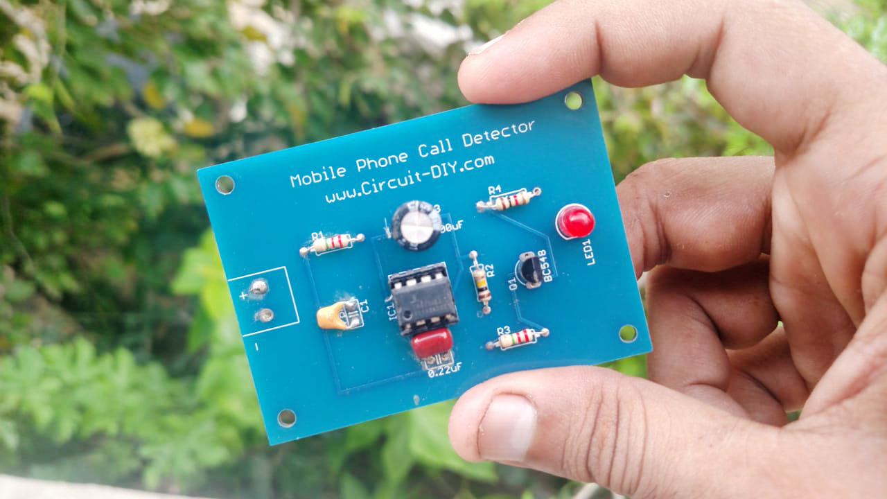
Call Detector Circuit are useful electronic circuits that can detect the presence of any transmitting RF mobile device nearby and gives a visual indication with respect to it. Basically, Cell-phone detector is a Frequency Detector or a Current Voltage Converter Circuit. With the development of communication technology, the requirement for cell phones has expanded dramatically. A cellphone generally transmits and receives indicators in the frequency range of 0.9 to 3GHz. So today in this tutorial, we will go through step-by-step instructions on “How to make a simple Mobile Phone Detector circuit” using a CAC3130 Operational amplifier
CA3130 is a BiMOS Operational Amplifier with MOSFET. The term BiMOS implies that it combines the advantage of both Bipolar and CMOS op-amp technology. CA3130 IC has the advantage of high bandwidth operation and less current consumption. Here, we are using the CAC3130 as a comparator.
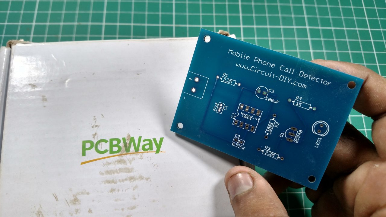
PCBWay commits to meeting the needs of its customers from different industries in terms of quality, delivery, cost-effectiveness, and any other demanding requests. As one of the most experienced PCB manufacturers in China. They pride themselves to be your best business partners as well as good friends in every aspect of your PCB needs.
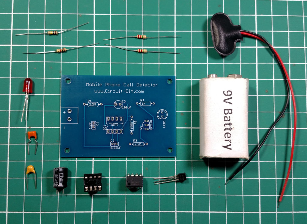
Hardware Required
The following components are required to make a Phone Detector Circuit
| S.no | Component | Value | Qty |
|---|---|---|---|
| 1. | IC | CA3010 | 1 |
| 2. | Transistor | BC548 | 1 |
| 3. | LED | – | 1 |
| 4. | Resistors | 2.2M, 100k, 1kΩ | 2, 1, 1 |
| 5. | Polar Capacitor | 0.22µF | 1 |
| 6. | Non Polar Capacitor | 100µF |
CA3130 Pinout

For a detailed description of pinout, dimension features, and specifications download the datasheet of CA3130
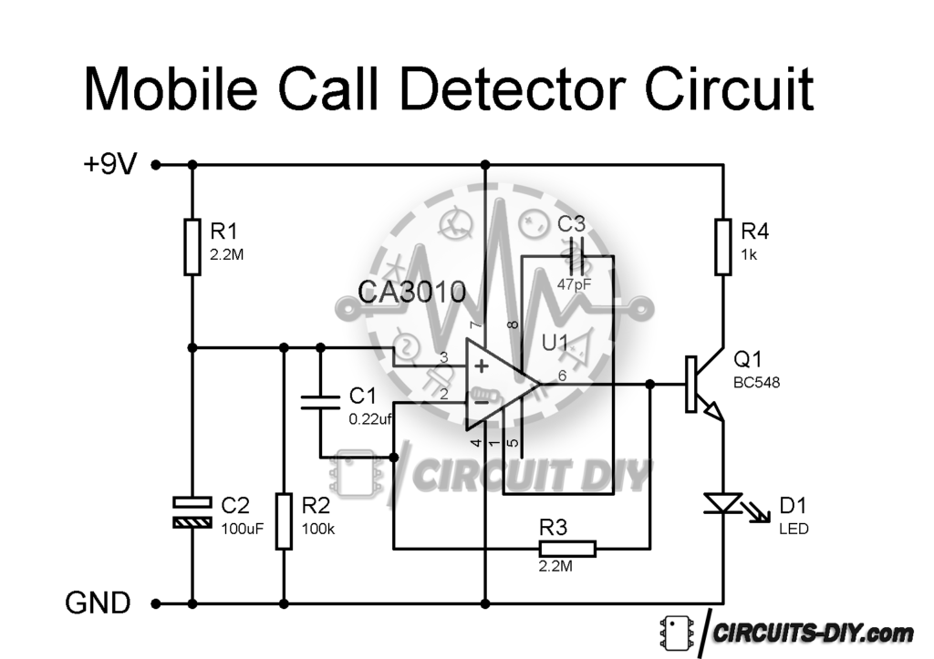
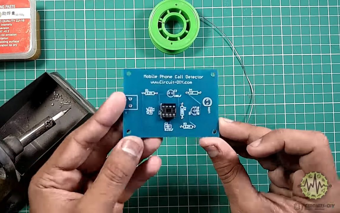
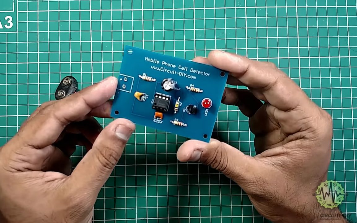
Phone Detector Circuit
Useful Steps
Follow all steps carefully from the video tutorial above this post (Highly Recommended).
1) Solder the 8-pin IC jacket on the PCB Board & place the CA3130 IC on it.
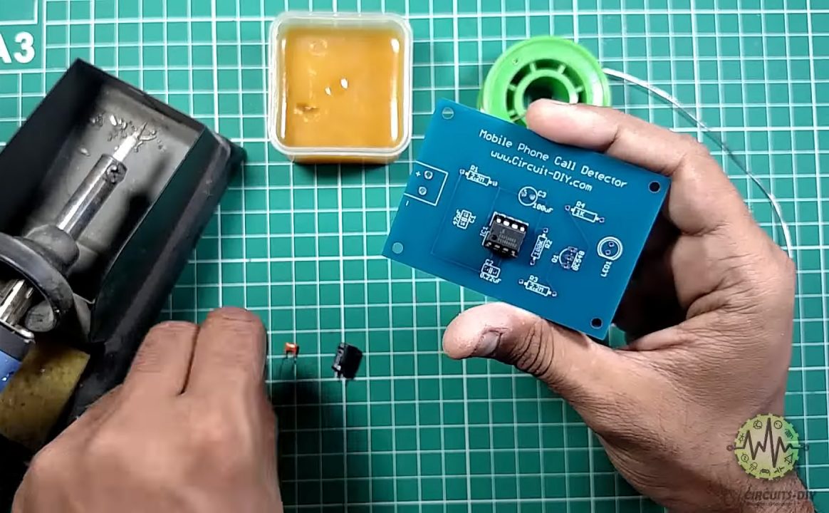
2) Solder Capacitors C1, C2 & C3 on the PCB Board.
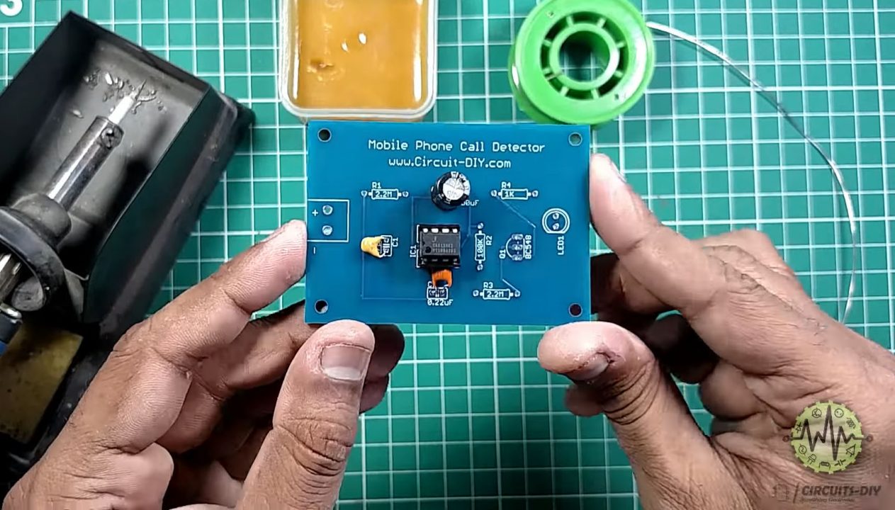
3) Solder Resistors (R1, R2, R3 & R4) on the PCB Board
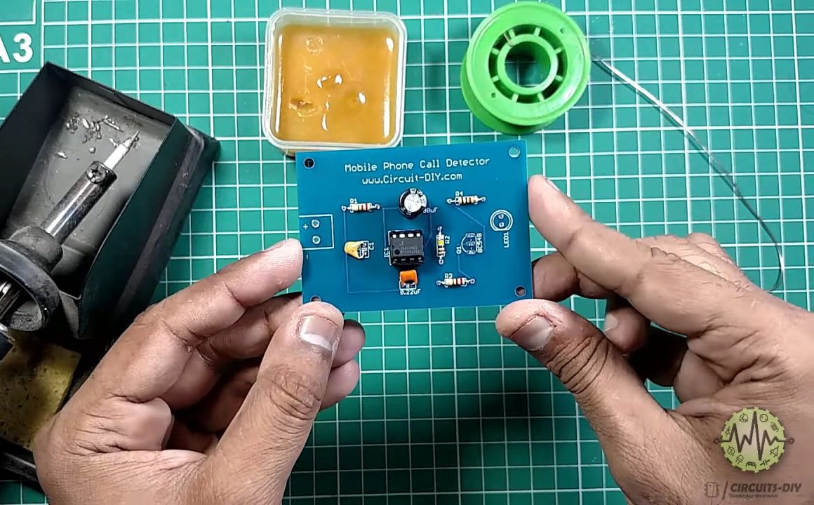
4) Solder the output LED of the BC548 Transistor onto the PCB Board.
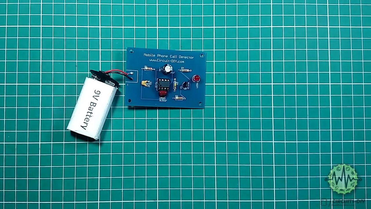
5) Solder the 9V Battery clip on the PCB board
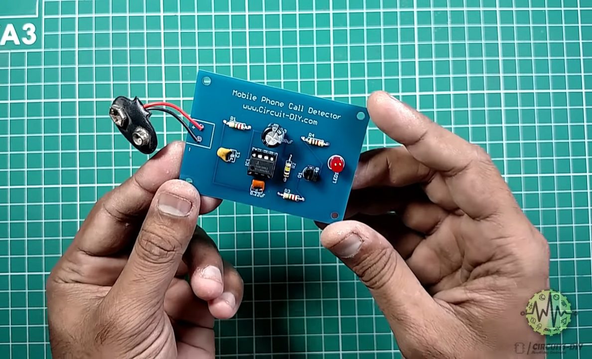
6) Connect a 9V battery & power up the circuit
7) Test & Inspect
Working Explanation
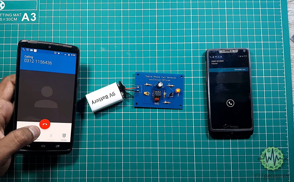
The working of this circuit is pretty simple. A 0.22uF capacitor captures the RF signal from any transmitting device namely a mobile phone. The capacitor leads act as a small gigahertz loop antenna to capture the transmitting RF signals from a mobile phone.
CA3130 functions as a current to voltage converter with a 0.22uF capacitor connected between its inverting and non-inverting input channels. When the cell phone detector signal is detected, the output of IC becomes high and low alternately according to the frequency of the signal as indicated by the LED.
Applications
- Usually used in places such as exam halls, military installations & places where the presence of a high-power RF transmitting device such as a mobile phone is prohibited.