Introduction
Safety is a major concern around the World. Many people employ gatekeepers, for this purpose but many times these guards also get hit by intruders. The LASER-Based Security Alarm is a safety purpose circuit that gives a warning or signal alert when an intruder or invaders try to invade a home, museum, office, bank, or any other place. So, in this article, we are going to make the LASER Security Alarm Circuit. One of the key components is LDR. So, before making the circuit, you just need to understand the working of LDR. LDR is the electronic component in which resistance get decreased as the intensity of light increases. it means that until the light falls on the LDR; the circuit doesn’t work due to increased resistance.
Components Required
| S.no | Components | Value | Qty |
|---|---|---|---|
| 1. | Timer IC | NE555 | 1 |
| 2 | Dual Operational Amplifier IC | LM358 | 1 |
| 3 | Potentiometer | 10K | 1 |
| 4 | NPN Transistor | BC547 | 1 |
| 5 | Resistor | 10k, 220 ohm | 3, 1 |
| 6 | LED | – | 1 |
| 7 | LDR | – | 1 |
| 8 | Buzzer | – | 1 |
| 9 | LASER | – | 1 |
| 10 | Switch | – | 1 |
| 11 | Capacitor | 10nf | 1 |
| 12 | Supply | 9V | 1 |
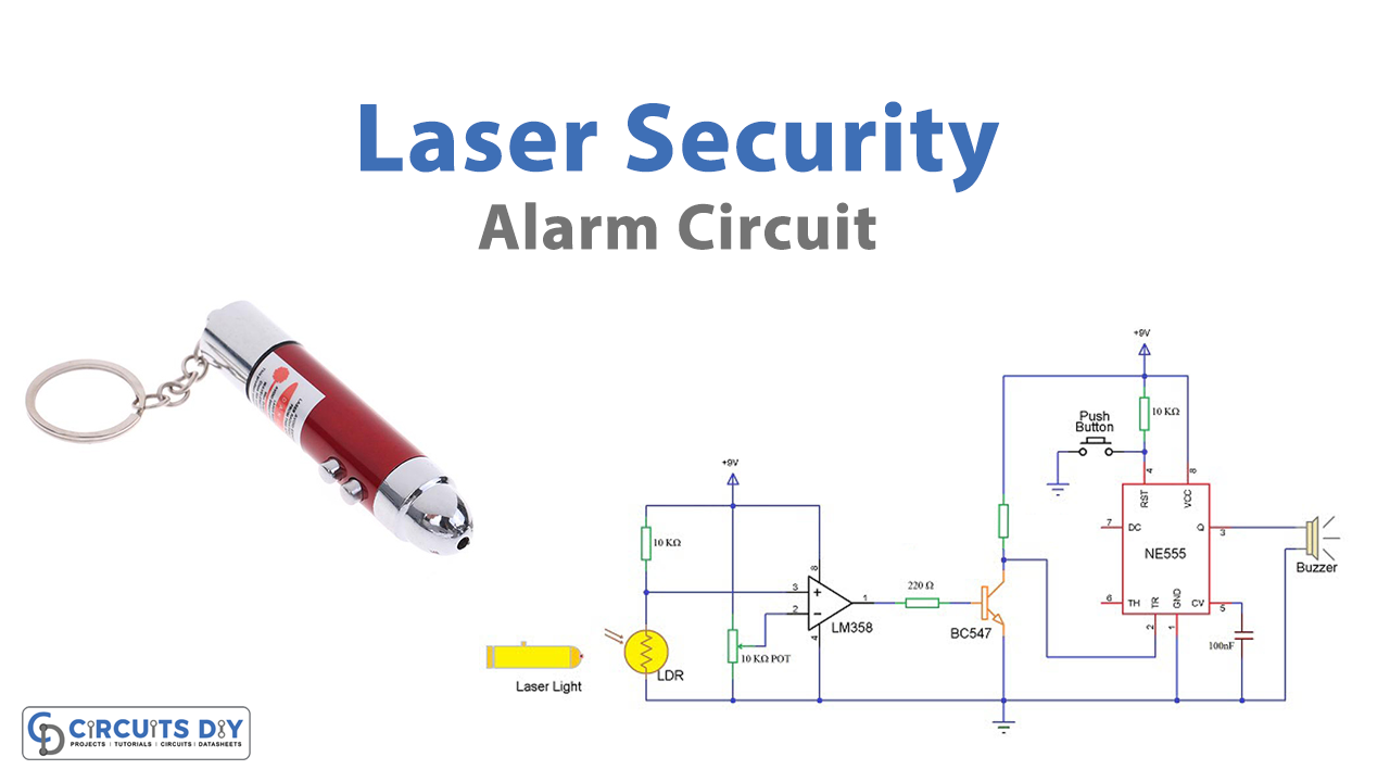
Circuit Diagram

Useful Steps
- Place LM358 and 555 timer IC on your board.

- Connect the potentiometer pins to pins 4 and 8 of IC385, and connect its middle pin to pin 2 of the same IC. Then connect a 10K resistor between pins 3 and 8, and LDR between Pin 3 and 4. Now place the transistor, and connect its emitter and collector pins to pins 1 and two of the 555 timer IC respectively.

- Connect 220 ohms of resistor between pin 1 of IC358 and the base of the transistor. Connect 10nf of a capacitor between pin 1 and pin 5 of IC555. Also, Connect a 10k resistor between pin 4 to pin 8 of 555 timers. Connect the other 10K resistor between pin 8 of 555 and the collector of the transistor. Then connect the micro switch to pins 4 and 1 of IC555

- Connect LED and buzzer in a way that their negative goes to pin and positive wired with pin 3 of IC555.

- Give battery positive to pin 8 and negative to pin 1 of an IC.

- Provide constant laser to the circuit.

Working Explanation
LDR works in the dark. So, when there is a constant light of laser falling on the LDR, the circuit doesn’t work. When someone comes between the LASER and LDR, its resistance gets decreased, and current flows through the circuits. The components work accordingly. Hence, the buzzer beeps and LED glows.
Applications
- Burgler/Intruder alarm.
- Security devices.
- Home and industrial automation systems.
- Motion detection, etc.


