
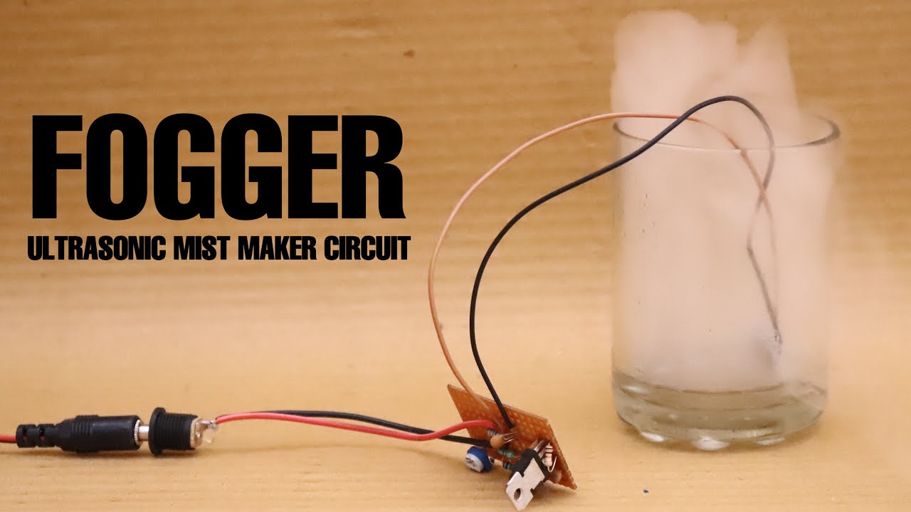
Fogger/Mist makers are an important part of today’s entertainment industry. They are utilized in almost each and every facet of media entertainment whether to create special effects for movies or to function as ceremonial aesthetics for live EDM concerts So, in this project, we are going to go over a step by step procedure on how to make A Fogger/Mist Maker Circuit at Home using a minimal number of components.
What is a Fogger/Mist ?
An electronic fogging machine is a device that emits a dense vapor that appears similar to fog or smoke. This artificial fog is most commonly used in professional entertainment applications, but smaller, more affordable fog machines are becoming common for personal use. Fog machines can also be found in use in a variety of industrial, training, and some military applications.
JLCPCB is the foremost PCB prototype & manufacturing company in china, providing us with the best service we have ever experienced regarding (Quality, Price Service & Time).
Hardware Components
You will need the following parts to build this project.
| S.no | Component | Value | Qty |
|---|---|---|---|
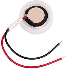
| 1. | Ultrasonic mist maker disc | 2.4MHz | 1 |
| 2. | NPN transistor | BU407 | 1 |
| 3. | Inductor | 22uH | 1 |
| 4. | Beaker | – | 1 |
| 5. | Wall Adapter | 24V | 1 |
| 6. | DC power jack | 3.5mm | 1 |
| 7. | Potentiometer | 5K | 1 |
| 8. | Capacitor | 1uF, 47nF, 1.5nF, 100pF | 1 |
| 9. | Resistor | 5.1K, 4.7K, 3.3K, 100 Ohm, 3.9 Ohm | 5 |
| 10. | Soldering iron | 45W-65W | 1 |
| 11. | Soldering Wire with Flux | – | 1 |
| 12. | Vero Board | – | 1 |
| 13. | Jumper Wires | – | As per need |
| 14. | DC Jack Socket | 3.5mm | 1 |
Ultrasonic Fogger Piezo Atomizer Disk
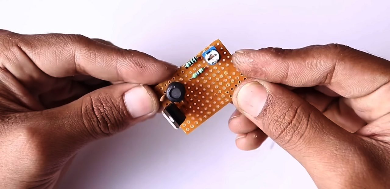
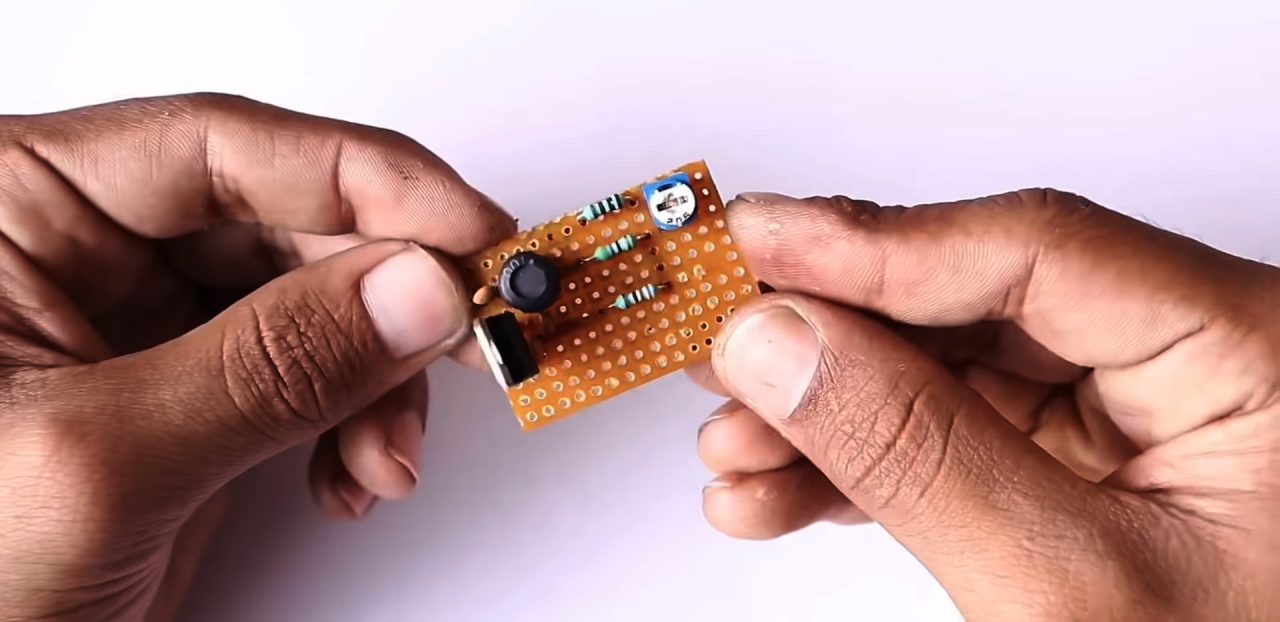
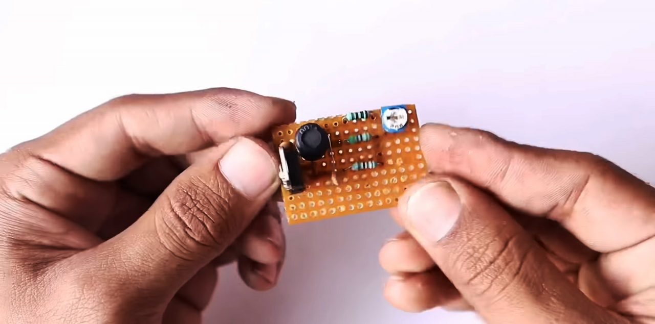
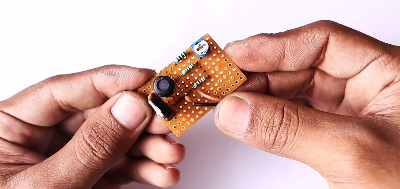
Useful Steps
Follow the steps as shown in the video above:
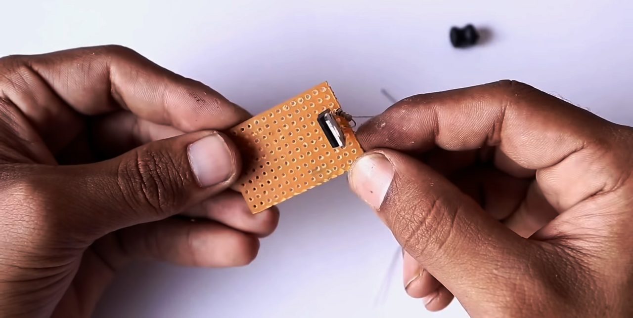
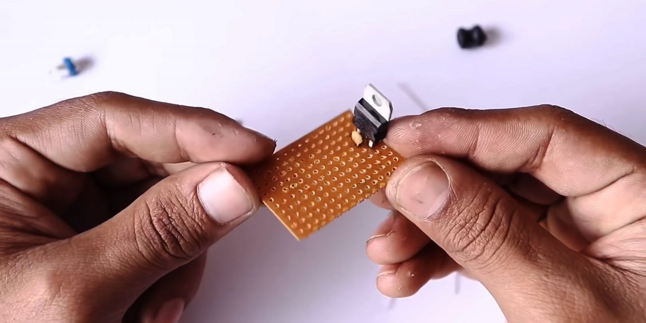
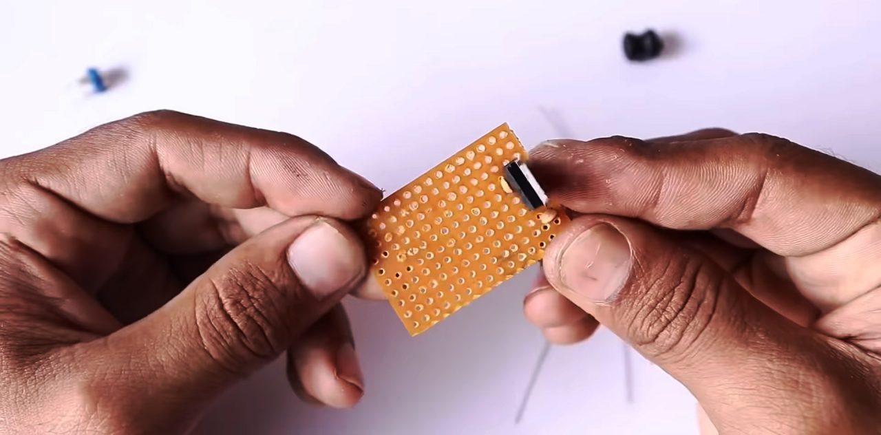
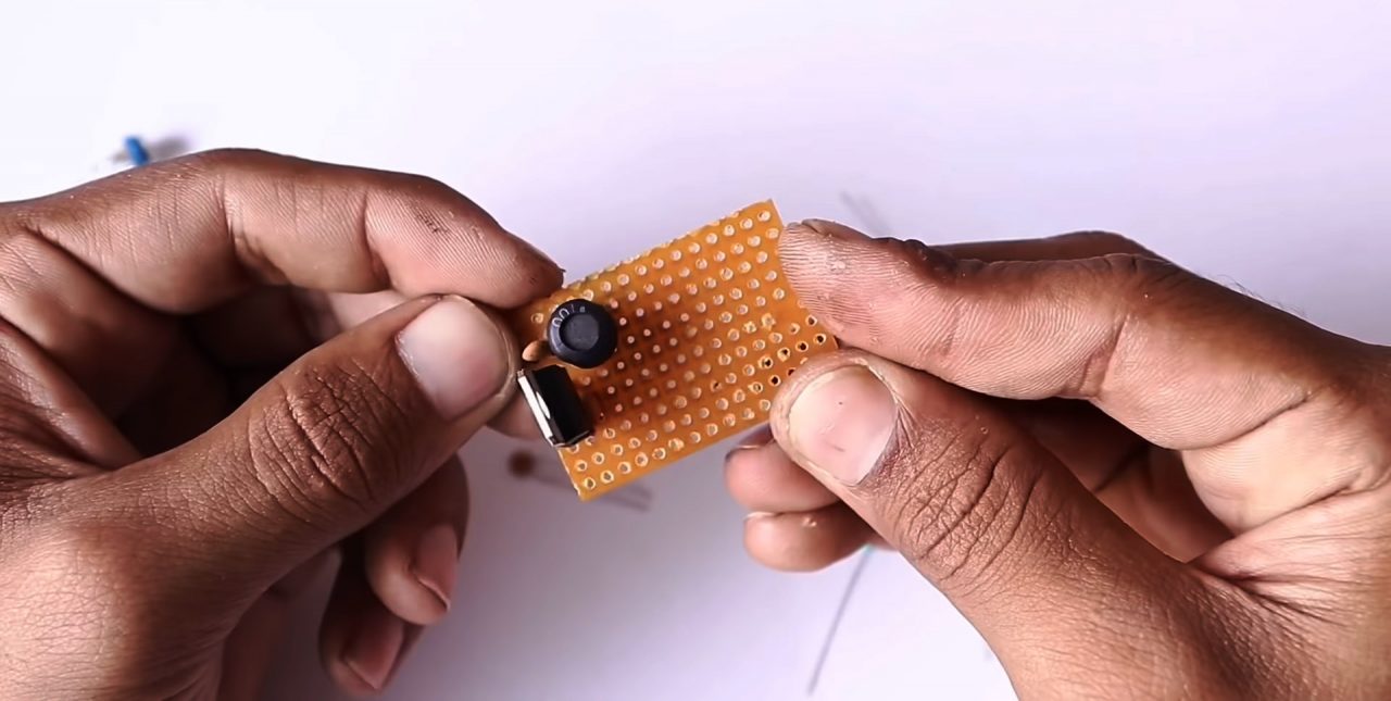
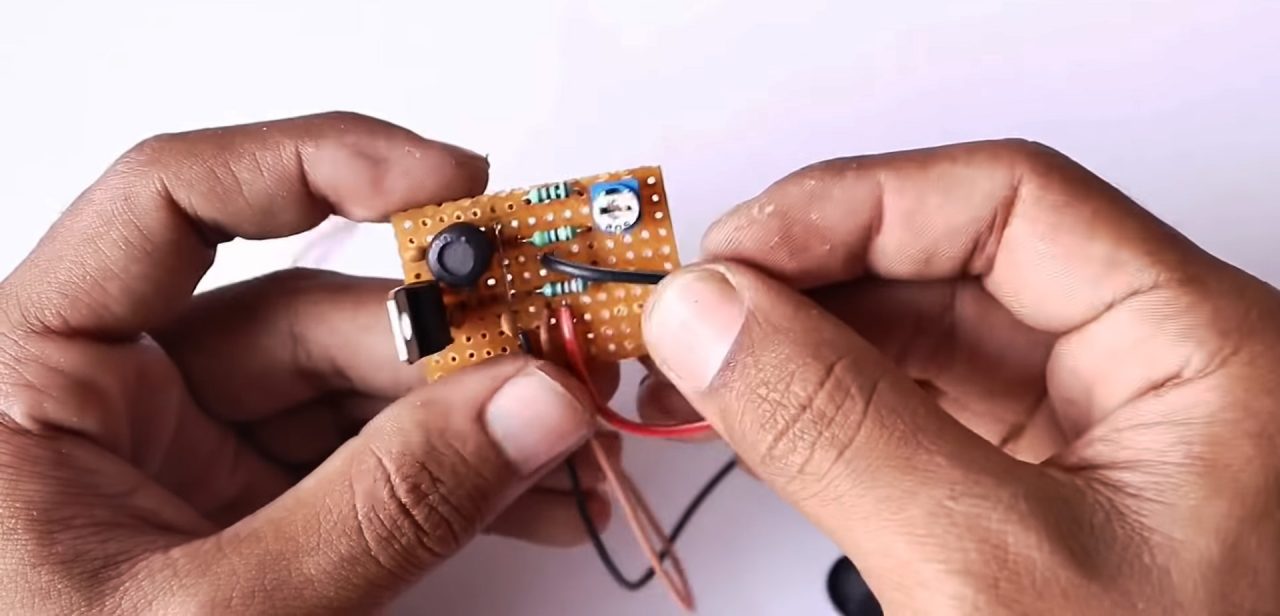
1) Solder the BU407 transistor on the vero board & solder a 3.9 Ohm resistor on the base of the transistor.
2) connect a 100nF capacitor between the base and collector of the transistor.
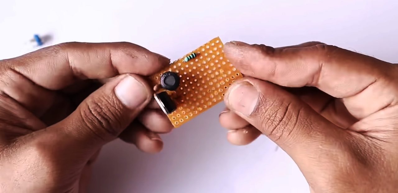
3) Connect a 47nF capacitor between the emitter of the transistor & 3.9 Ohms resistor. After that connect a 22uH inductor coil on the emitter of the transistor.
4) Solder a 1nF capacitor between the collector & emitter of the transistor. After that connect a 100 Ohm resistor in series 3.9 Ohms resistor.
5) Connect a 5K pot to adjust preset with the 100 Ohm resistor. After solder a 4.7K resistor between pot preset and GND of the circuit.
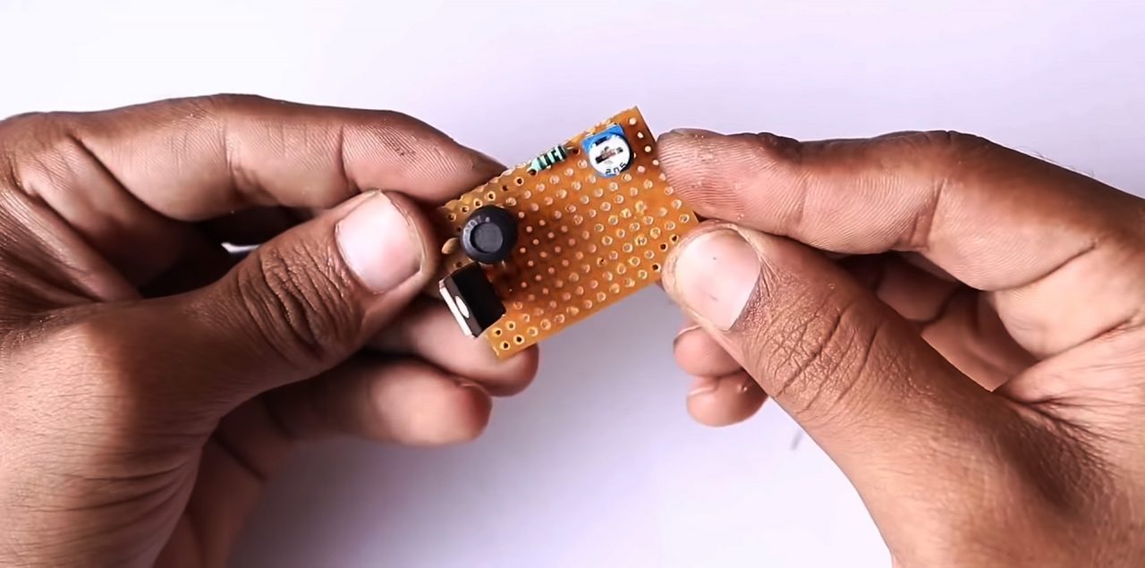
6) solder a 3.3K resistor between the pot and the collector of the transistor.
7) Connect a 47nF capacitor between the between the 3.9 Ohm & 100 Ohm resistor.
8) Solder the +ve terminal of the piezo atomizer disc on the collector of the transistor & the -ve terminal with the 47nF capcitor.
9) Connect the +ve terminal of the DC input socket on the collector of the transistor & -ve terminal to the 22uH inductor coil.
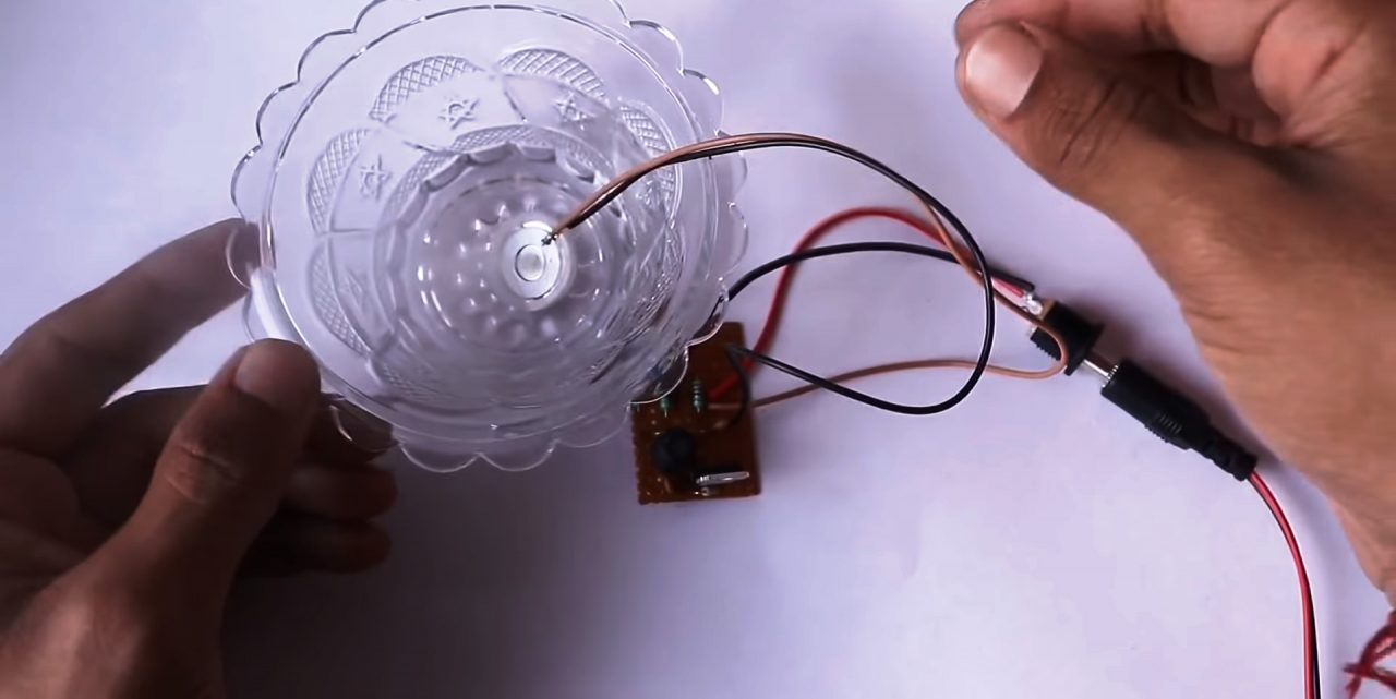
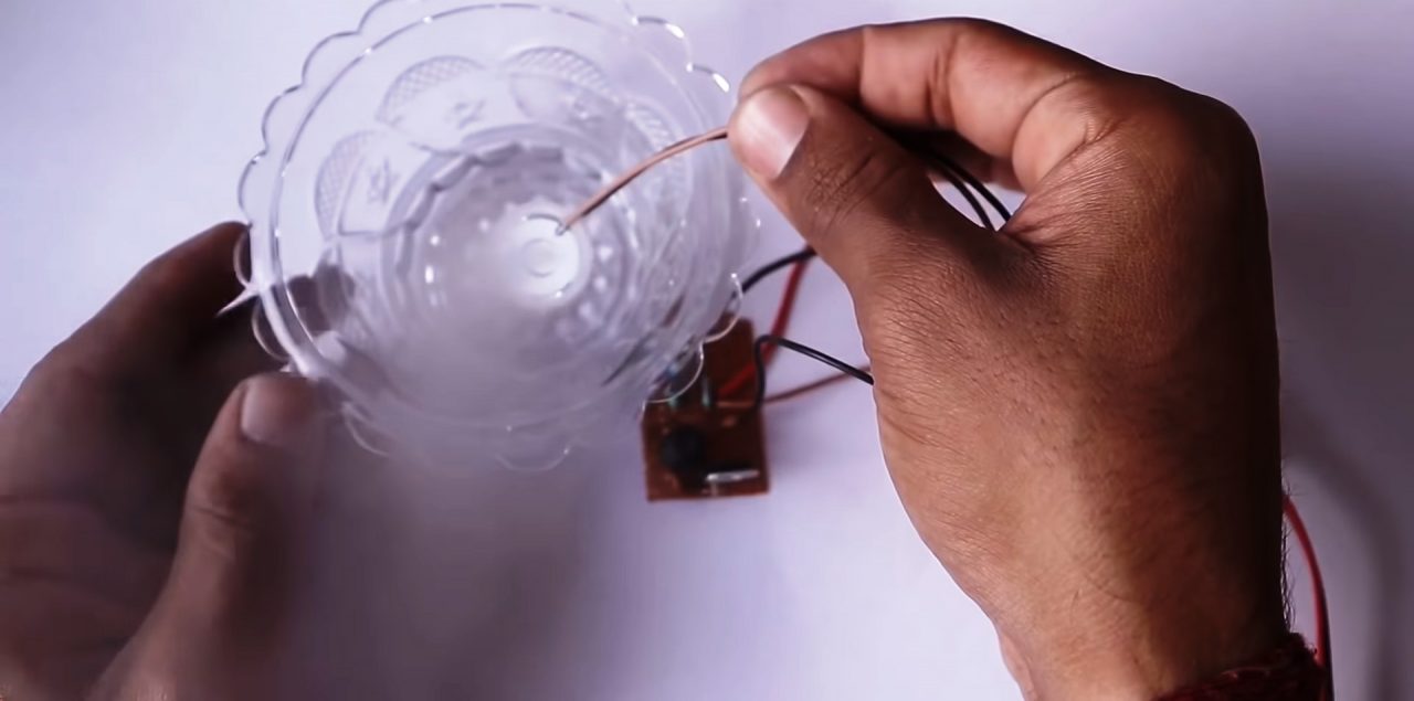
10) fill up a bowl with some water, enough so that the piezo disc fully immersed in the liquid. Power up & test the circuit.
Circuit Diagram
Working Explanation
The working of this revolves around triggering an ultrasonic piezoelectric atomizer using a BU407 NPN transistor as a switch to produce a fine mist of any given liquid by converting high-frequency sound waves into mechanical energy that is transferred into the liquid, thus creating standing waves. As the liquid exits the atomizing surface of the disc, it’s broken into a fine mist of uniform micron-sized droplets, creating a fine mist.
The intensity of mist maker can be controlled by using the variable resistor VR1, which is also used to decide the preset of the circuit.
Applications
- It is mostly used in live music concerts, TV shows & movie productions.
Related posts:
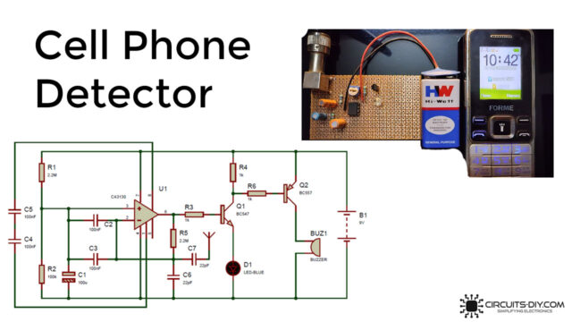 Cell Phone Detector circuit
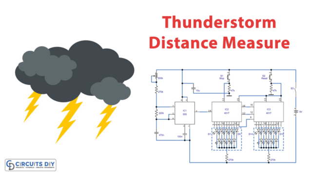 Measuring Thunderstorm Distance using an Electronic Circuit
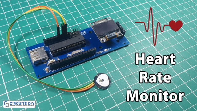 Heart Rate Pulse Sensor - BPM Meter using OLED & ESP32
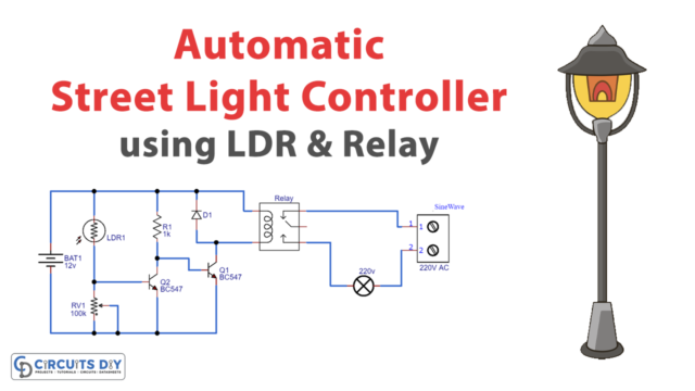 Automatic Street Light Controller Circuit Using Relays and LDR
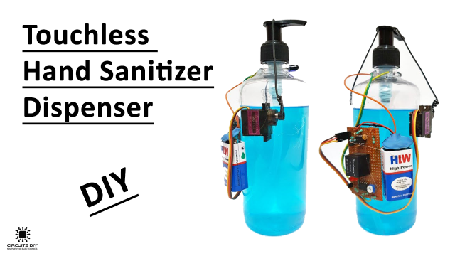 How To Make A Touchless Hand Sanitizer Dispenser - DIY Project
 Obstacle Detector by IR Sensor & ATmega328 Arduino


