Plasma Spark Generator?
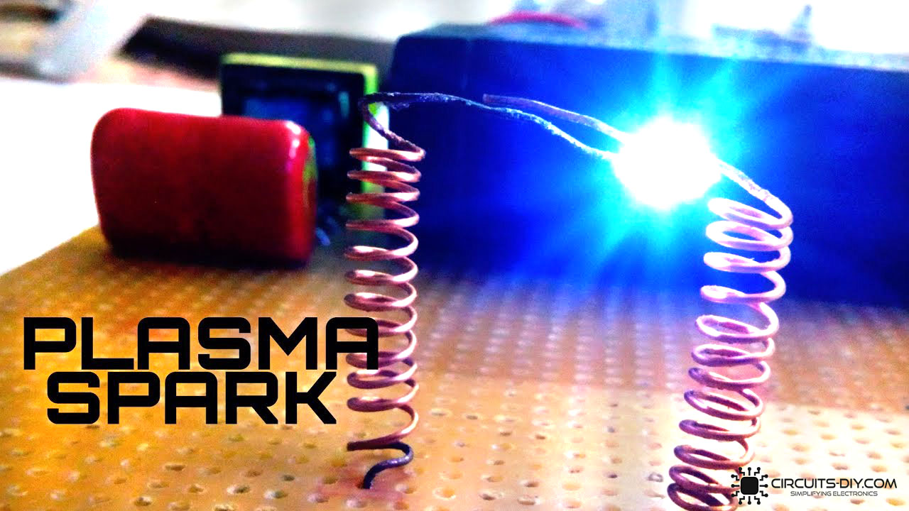
Plasma spark generators are simple electronic circuits designed to exhibit a high-power pulse circuit, which stores incoming electrical energy from the ignition system and releases the stored energy in a powerful pulse of power. They are commonly used in designing electric bug zappers to exterminate pests & insects from common households and offices. So, In today’s project, we are going to go over a step-by-step procedure on how to create a Plasma Spark Generator, using a 4V DC Battery & a small number of other components.
JLCPCB is the foremost PCB prototype & manufacturing company in china, providing us with the best service we have ever experienced regarding (Quality, Price Service & Time).
Hardware Components
The following components are required to make Plasma Spark Generator Project
| S.no | Component | Value | Qty |
|---|---|---|---|
| 1. | Film Capacitor | 105J | 1 |
| 2. | SM Transformer | 12V/220V, 3A | 1 |
| 3. | Transistors | BC547 | 1 |
| 4. | Capacitors | 47pF | 3 |
| 5. | Enameled copper wire | – | 1 meter |
| 6. | Toggle switch | – | 1 |
| 7. | Resistors | 1K | 2 |
| 8. | Diodes | 1N4007 | 3 |
| 9. | DC Battery with clips | 4V | 1 |
| 10. | Soldering Iron | 45W – 65W | 1 |
| 11. | Soldering Wire with Flux | – | 1 |
| 12. | Jumper Wires | – | As per need |
BC547 Pinout
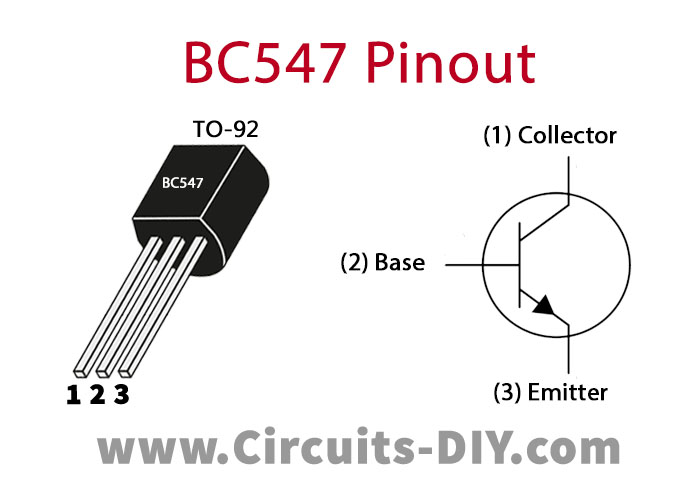
For a detailed description of pinout, dimension features, and specifications download the datasheet of BC547
Useful Steps
1) Solder the SM transformer on the Veroboard. After that, Solder the base & collector terminal of the BC547 transistor with primary terminals of the transformer.

2) Solder the 1K resistors on the Veroboard.

3) Solder the capacitors & diodes on the Veroboard. After that, solder the Film capacitor & the LED on the Veroboard.

4) After that solder the toggle switch on the Veroboard.

5) Solder the 4V battery on the Veroboard.
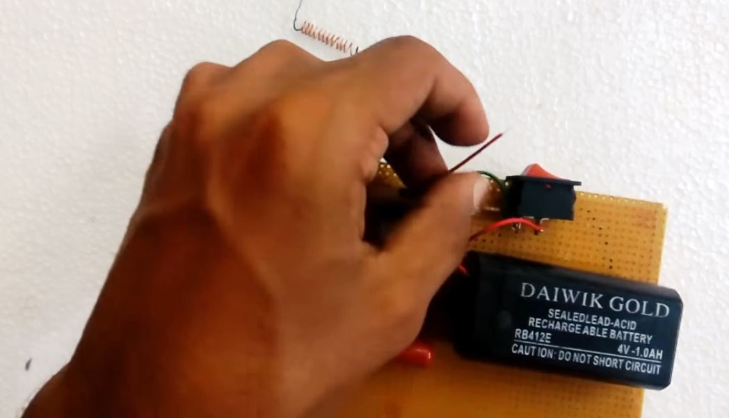
6) Coil two pieces of enameled copper wire with their ends pointed in almost close contact with each other. After that, solder the copper coils on the Veroboard.
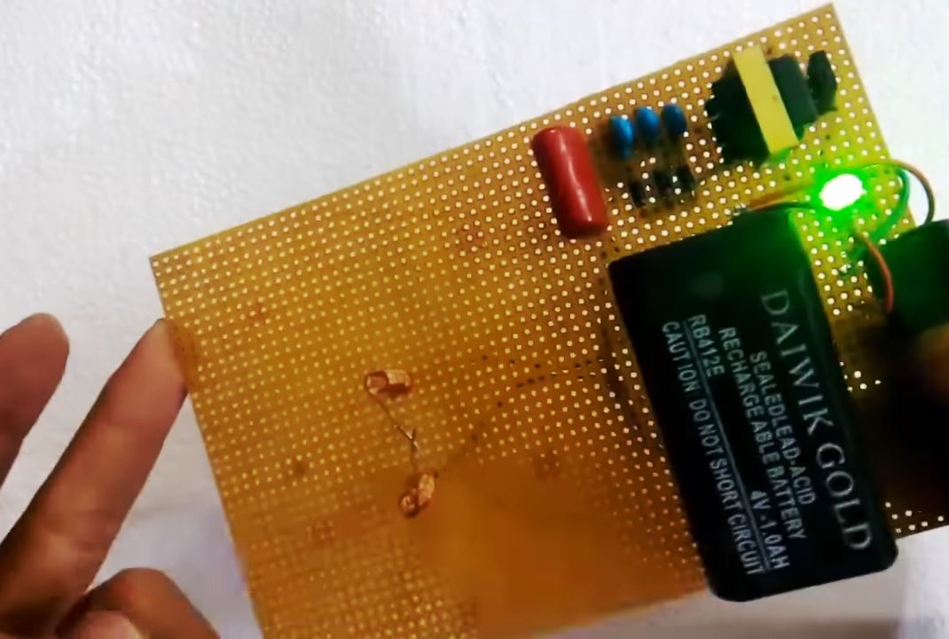
7) Power up & test the circuit.
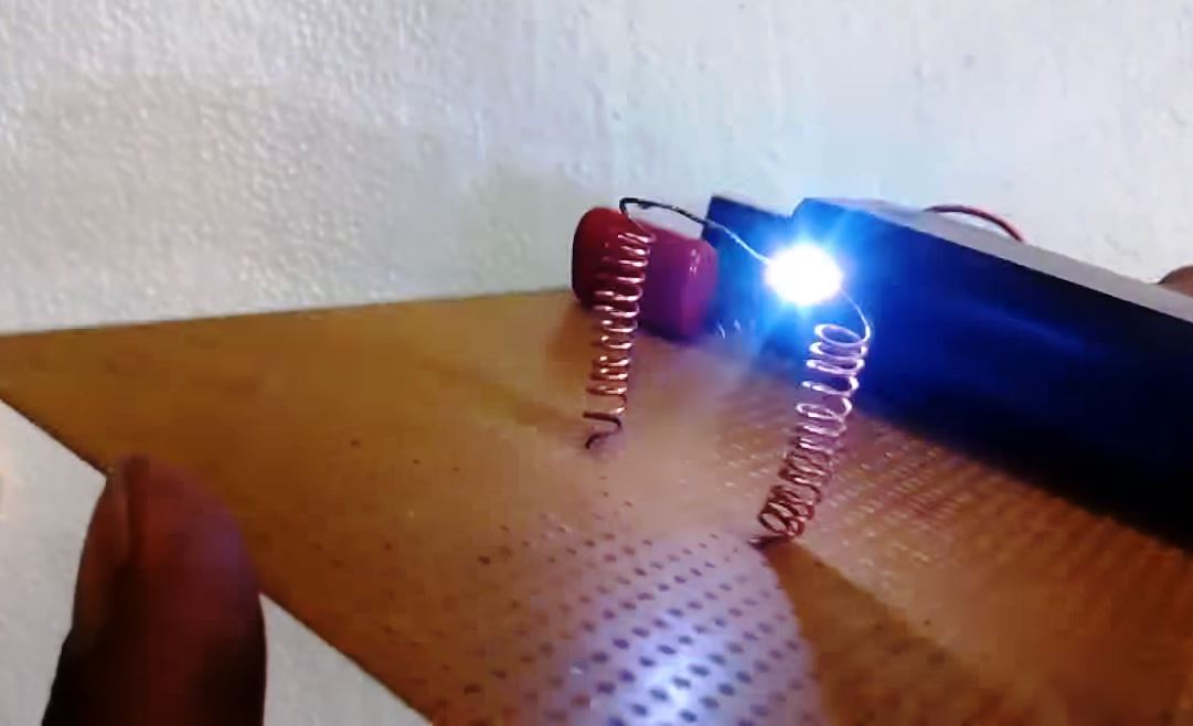
Working Explanation
When the ignition signal is sent to the coil, it begins to ionize the spark gap. This means that the voltage builds in the gap until a spark can be formed. During this ionization phase, which lasts about 5 millionths of a second, the incoming voltage (which has nowhere to go) heats up ignition components (copper coil).
When the ignition voltage overcomes the resistance in the coil spark gap, the spark is created with an initial discharge of approximately 50 watts. Once created, the spark resides between the ends of the copper coil at very low power for over a period of 30 millionths of a second.
Applications
- Usually used in designing insect repellent devices used for pest control such as Bug zapping lanterns & rackets.


