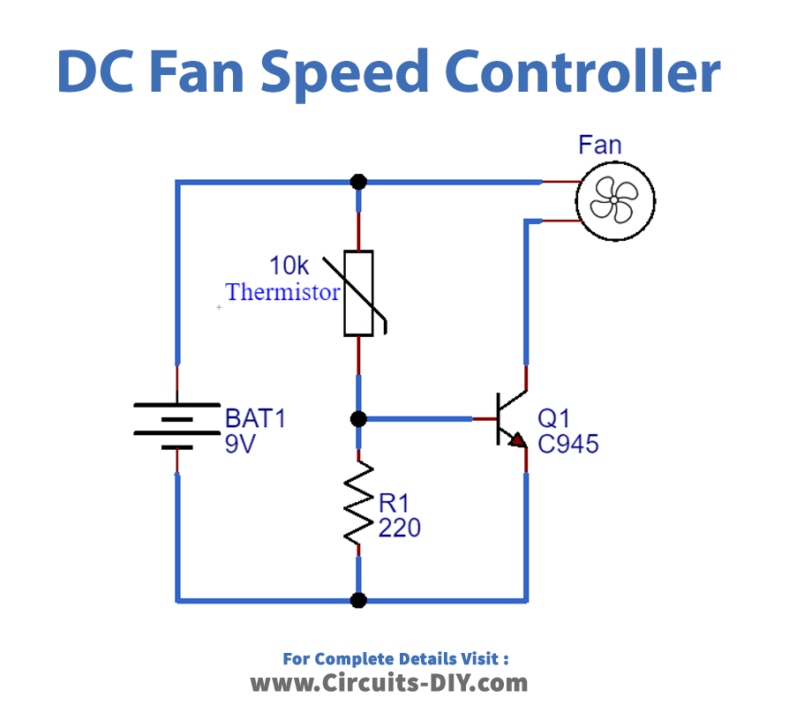
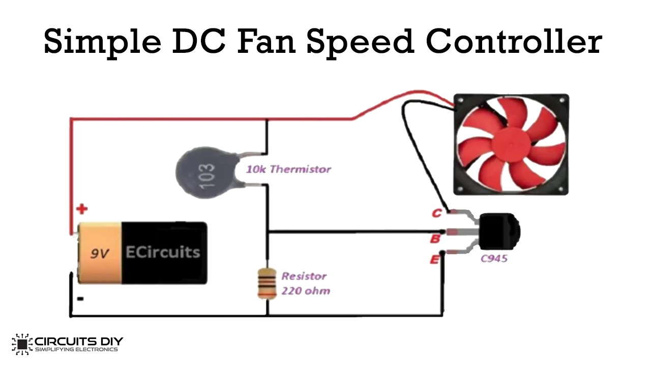
In this tutorial, we are going to control the speed of a DC Fan by using a thermistor. The main aim of a temperature control sensor circuit is to indicate a temperature or control a temperature. A Fan control temperature sensor circuit exploits the property of a sensor to control the speed of a fan. A sensor is basically a type of transducer which is a type of device that converts one form of energy to another.
The important component of a Fan controlled temperature sensor circuit is a thermistor. The fan control temperature sensor circuit reduces power consumption and also helps people to control the speed of a fan.

Hardware Components
The following components are required to make DC Fan Speed Controller Circuit
| S.No | Component | Value | Qty |
|---|---|---|---|
| 1. | Breadboard | – | 1 |
| 2. | Battery | 9v | 1 |
| 3. | Connecting Wires | – | 1 |
| 4. | DC Fan | – | 1 |
| 5. | Thermistor | 10k | 1 |
| 6. | NPN Transistor | C945 | 1 |
| 7. | Resistor | 220 ohms | 1 |
C945 Pinout

For a detailed description of pinout, dimension features, and specifications download the datasheet of C945
DC Fan Speed Control Circuit

Working Explanation
The principle of the circuit is to monitor and control the temperature. Whenever the temperature of a device increases or decreases the speed of a fan changes accordingly. So the temperature control sensor works as a cooling device. The resistance of a thermistor decreases when there is an increase in temperature. So the electrical conductivity also increases which results in the increment of voltage.
This causes the speed of a fan to increase. Hence, it is possible to control the speed of a fan when the temperature of a device varies. By making slight adjustments in a circuit, it can also be used to control the room temperature.
Application
- The temperature sensor circuit monitors the changes in an environment.
- It has various applications in different industries and electronic devices.


