
Introduction
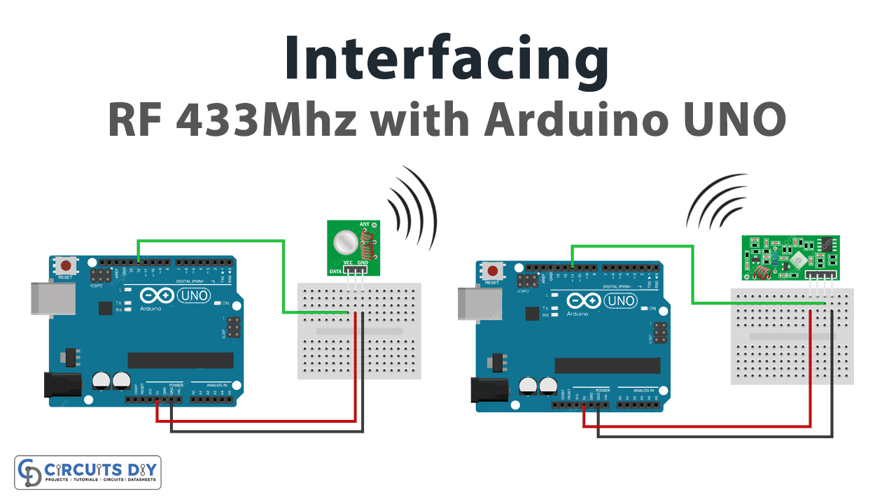
Are you worried about any of your projects because you want a wireless connection? So, if you want the wireless connection within the range of 433MHz of frequency, then read out this article. Because, In this tutorial, we are going to interface “433MHz RF Tx-Rx Modules with Arduino UNO”. To understand this, take the example of radio and TV channels. TV channels, radios, etc use the RF band for broadcasting. And for this purpose, they need Radiofrequency devices like transmitters and receivers.
This works on the principle of transmission and receiving of data from one device to another. In other words, the module has a receiver that accepts the data or information coming from the transmitter module. RF modules work on different ranges. In our case the module range is 433MHz.
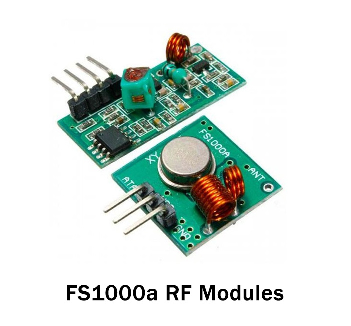
Features of Transmitter Module
- The operating voltage range is from 3V to 12V.
- The module has an operating frequency of 433MHz.
- It draws a current of 5.5mA.
- The module employs the amplitude shift key method for transmission.
- The module is of cheaper in cost
Features of Reciever Module
- The maximum operating voltage is 5V.
- The module has an operating frequency of 433MHz.
- It draws a current of 5.5mA.
- The data transmission speed is about 10kbps.
- it has the saw resonator circuit type.
- The module is of low cost.
Hardware Required
Circuit Diagram
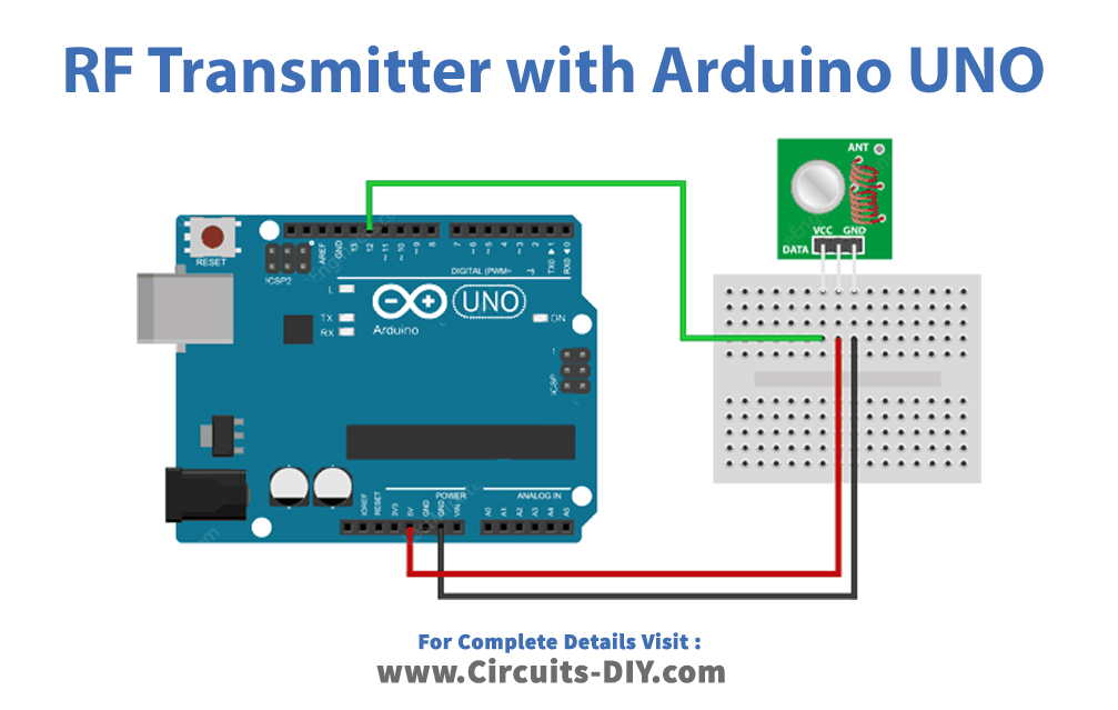
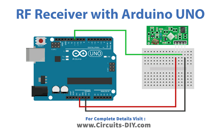
Connection Table
| Arduino | RF TX | RF RX |
|---|---|---|
| VCC | VCC | VCC |
| GND | GND | GND |
| D11 | – | DAT |
| D12 | DAT | – |
Arduino Code
For 433MHz RF Transmitter
// Include RadioHead Amplitude Shift Keying Library
#include <RH_ASK.h>
// Include dependant SPI Library
#include <SPI.h>

// Create Amplitude Shift Keying Object
RH_ASK rf_driver;

void setup()
{
    // Initialize ASK Object
    rf_driver.init();
}

void loop()
{
    const char *msg = "Hello World";
    rf_driver.send((uint8_t *)msg, strlen(msg));
    rf_driver.waitPacketSent();
    delay(1000);
}
For 433MHz RF Receiver
// Include RadioHead Amplitude Shift Keying Library
#include <RH_ASK.h>
// Include dependant SPI Library
#include <SPI.h>

// Create Amplitude Shift Keying Object
RH_ASK rf_driver;

void setup()
{
    // Initialize ASK Object
    rf_driver.init();
    // Setup Serial Monitor
    Serial.begin(9600);
}

void loop()
{
    // Set buffer to size of expected message
    uint8_t buf[11];
    uint8_t buflen = sizeof(buf);
    // Check if received packet is correct size
    if (rf_driver.recv(buf, &buflen))
    {

      // Message received with valid checksum
      Serial.print("Message Received: ");
      Serial.println((char*)buf);
    }
}
Working Explanation
Connect the Tx-Rx Modules with Arduino according to the diagrams available above in this article. After that to transmit the message copy the above code of transmitter and paste it into your Arduino UNO. To recieve the message uplaod the reciever code. Open the serial monitor and you will see the transmitted message on the serial monitor.
Code Explanation
For 433MHz RF Transmitter:
Download and install the RadioHead ASK library. You can download the library from:
https://github.com/sparkfun/SparkFun_RadioHead_Arduino_Library
- Include the downloaded library. Also, include the SPI library to communicate with the external device. Create an RH_ASK object called rf_driver to access some Radiohead relate functions.
- After that in the void setup, initialize the object by using rf_driver. init( ).
- In the void loop, prepare the message. The message is the simple text, stored in the character pointer called msg. Send the message by using send( ) function. Use the waitPacketSent( ) function to wait until the previous message is transmitted. Give some delay to transmit the new message.
For 433MHz RF Receiver:
- Like the code of transmitter, for the reciever code include the downloaded RadioHead library. In the same vein, include the SPI and create an RH_ASK object called rf_driver to access Radiohead relate functions.
- Similarly like the tranmitter sketch, in void setup, initialize the radio head object
- In the void loop, create the buffer. The size of the buffer must be as the same size of transmiter’s message. Remember that punctuations and spcaes also get count in the size. Create the if condition and call the function recv( ) to turn on the reciever. Hence make the program that if there is any message avialable, it would print “Message Recieved” . After that use Serial. println((char*)buf) to print the recieved message on the Serial monitor.
Related posts:
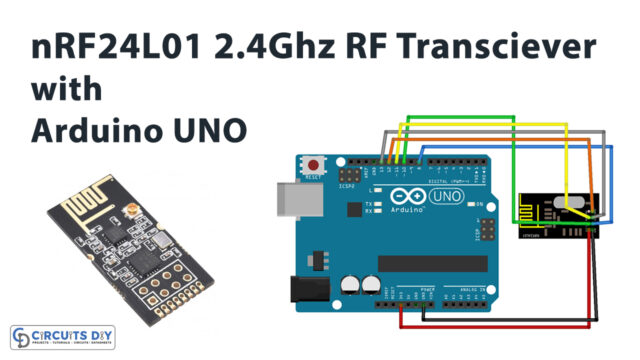 Interface nRF24L01 – 2.4GHz RF Transceiver Module With Arduino UNO
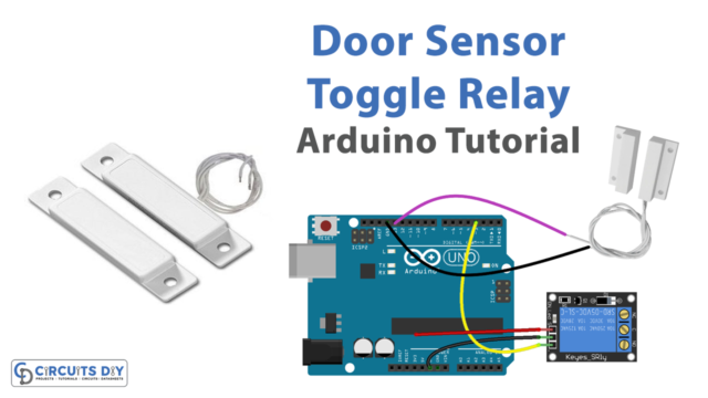 Door Sensor Toggle Relay - Arduino Tutorial
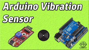 How to interface Vibration Sensor (SW-420) with Arduino
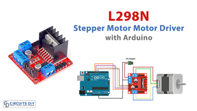 Control Stepper Motor with L298N Motor Driver & Arduino
 Temperature Sensor with OLED - Arduino Tutorial
 Arduino - Door Open - Send Email Notification


