Introduction
Visualize a world where you have peace of mind knowing that a state-of-the-art intruder alarm system safeguards your house. This circuit is made to pick up even the slightest movement and sound a loud alarm, which will scare off burglars and warn you of any possible danger.
Plus, it can be integrated with your smart home system, allowing you to remotely monitor and control the alarm from your phone or tablet. The home intruder alarm circuit is the best way to protect your home and family. It uses cutting-edge technology and has a sleek design. Let’s try to make it in this article!
Hardware Required
You will require the following hardware for Home Intruder Alarm Circuit.
| S.no | Component | Value | Qty |
|---|---|---|---|
| 1. | IC | CD4001 | 4 |
| 2. | Capacitor | 0.1 | 2 |
| 3. | Polar Capacitor | 10uF | 7 |
| 4. | Transistor | 2N3905 | 1 |
| 5. | Diode | 1N419 | 2 |
| 6. | Battery | 12V | 1 |
| 7. | Resistor | 4m7, 22k, 1k, 100k, 4k7 | 2, 2, 2, 6, 1 |
| 8. | Switch | – | 5 |
Steps to make.
Follow the given steps to build the intruder alarm circuit.
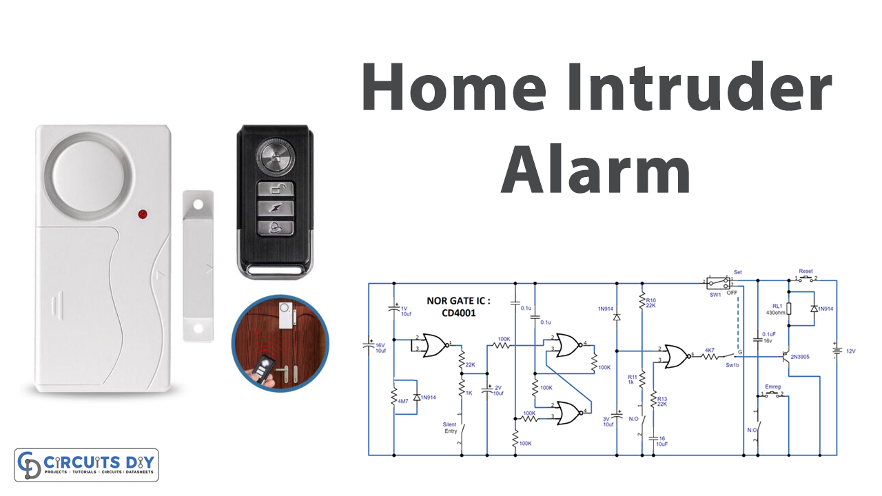
Circuit Diagram.

Connections
Here is a summary of the connections of the circuit:
- Capacitor C2 is connected to Resistor R1
- IC1/1 input is connected to the series loop and silent entry switch
- IC1/2 and IC1/3 are connected to form an RS flip-flop circuit
- IC1/3 output is connected to capacitor C6
- The emergency switch is connected across points F and D
- Diodes D1 and D2 are connected to discharge capacitors C2 and C6, respectively.
- Resistors R6, R7, and R12 are connected to protect the CMOS IC against voltages exceeding the supply rails.
- Capacitors C3, C5, C7, and C8 are connected to protect against false activation.
Modes of Circuit
The Home Intruder Alarm Circuit uses a CMOS IC to provide a low-power drain. Making it suitable for battery operation. The high noise immunity of CMOS also makes it less vulnerable to false alarms caused by external factors such as lightning flashes. The circuit has three modes of operation: Alarm mode, Silent Entry mode, and Emergency mode.
- In Alarm mode, microswitches or reed relays are fitted to closed contacts when doors or windows are closed. These contacts are wired in a series loop. If any door or window is opened, the loop will be broken and trigger the alarm.
- In Silent Entry mode, the owner is given 30 seconds to open and close the front door before the alarm mode is activated. It also allows the owner 30 seconds to disable the alarm upon entering the premises through the front door.
- In Emergency mode, any contact closure will immediately sound the alarm.
Working Explanation
The circuit temporarily boosts the input of IC1/1 to +12V. The voltage then decreases gradually through R1 and C1, reaching zero. The output of IC1/1 will be zero when the input exceeds 7V and +12V when the input is less than 5V, with a small linear transition region around 6V. C2 and R1 add a 30-second delay, which can be changed by making changes to C2. During this delay, opening or closing the silent entry door will not affect the level displayed on pin 6 of IC1/2.
An RS flip-flop is formed by IC1/2 and IC1/3, with the control inputs (pins 6 and 9) typically at low voltage. When the circuit is first turned on, C4 briefly pulls pin 9 up to +12V before letting it go back to 0. This gives IC1/3 a “1” input, which makes the output low. As pins 7 and 5 are also at zero, the output of IC1/2 will be high, and the flip-flop will be locked in this state.
The only way to reverse the flip-flop is for the input to pin 6 to go high, but during the first 30 seconds, the output of IC1/1 is low, so opening or closing the silent entry door will not affect the flip-flop. After 30 seconds, opening the silent entry door will activate the flip-flop and switch on the alarm.
The high output of IC1/3 allows C6 to charge to +12V gradually through R9. When this voltage reaches 6 volts (around 30 seconds), it triggers the output of IC1/4 to go low (assuming the normal alarm loop is closed). The low output of IC1/4 activates relay RL1 through emitter follower Q1, triggering the home intruder alarm circuit.
When the relay closes, contacts RL1/1 latch on, and the only way to reset it is by removing power through PB1. If the normal guard loop is broken while the alarm is active, a “1” is presented to pin 13 of IC1/4, causing the output to go low and activate the relay. When the emergency switch is closed, Q1’s base is brought to zero, and the relay closes and latches, regardless of the alarm’s status.
When the SW1 is turned off, diodes D1 and D2 discharge capacitors C2 and C6 through SW1. This makes sure that the 30-second delay works. R6, R7, and R12 protect the CMOS IC from voltages exceeding the supply rails, and C3, C5, C7, and C8 provide additional protection against false activations from lightning, etc.
Final Words
A Home Intruder Alarm Circuit is analyzed in this article. The circuit is simple and employs low-priced components. We hope you learned something new about this circuit from this post and found it helpful. Please don’t hesitate to contact us if you have any queries or feedback.