Introduction
In this tutorial, we will make “HMC5883L 3-Axis Compass Module Interfacing with Arduino”. HMC5883L is a magnetometer. A magnetometer, often known as a compass, is a type of navigation equipment that evaluates the strength of the magnetic field or the magnetic dipole moment. A magnetometer is a device containing a sensor that detects magnetic flux density. Magnetometers measure a magnetic field’s direction, strength, or relative fluctuation at a specific area. Magnetometers are often used to calibrate electromagnets & permanent magnets as well as to determine the magnetism of a substance.
Brief Overview
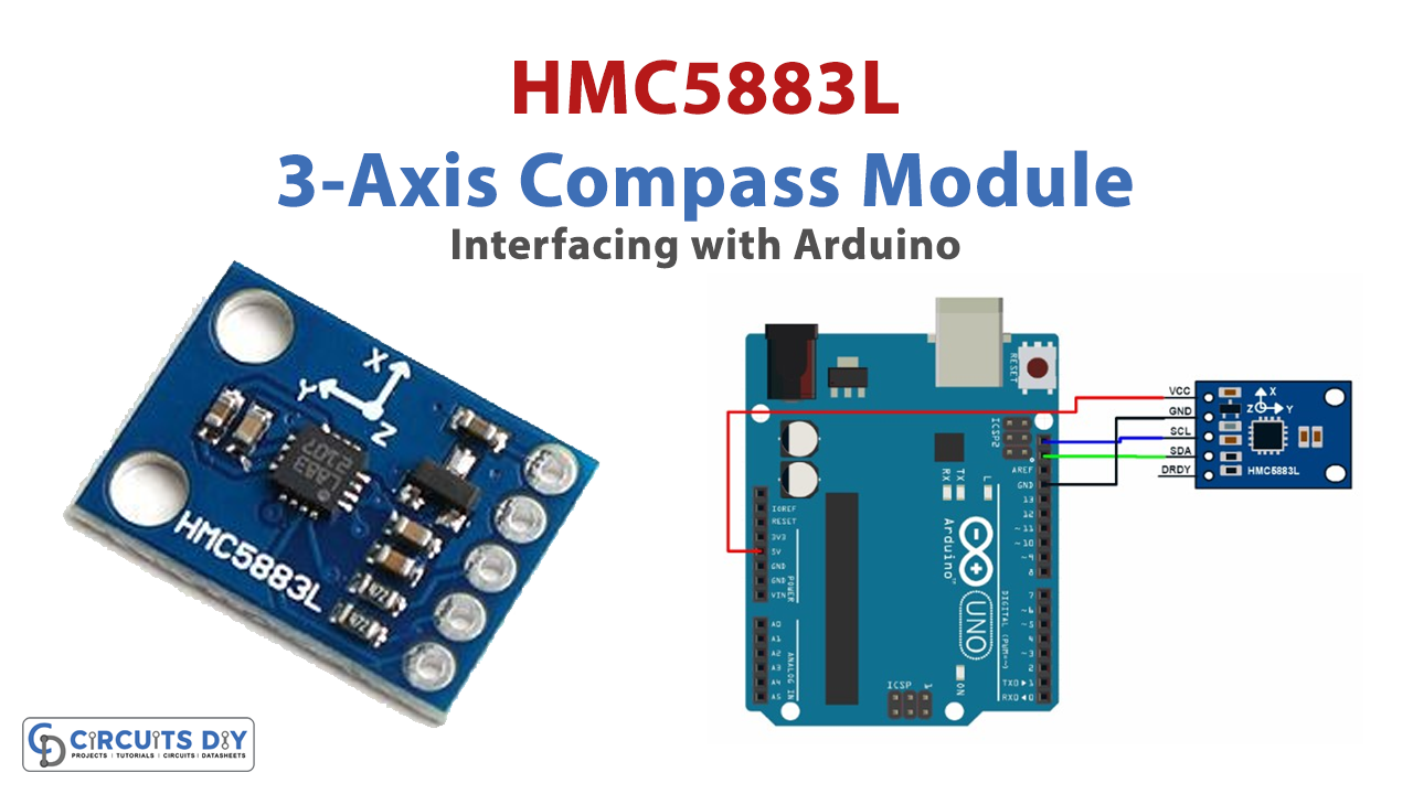
Honeywell’s HMC5883L magnetometer module employs anisotropic magnetoresistive technology. It is a multichip module that acts as a digital compass IC to determine the direction and magnitude of the magnetic field along the X, Y, and Z axes. The magnetic field is converted into differential voltage output on three-axis pins via the HMC5883L module.
Features of the HMC5883L Module
- It operates with a DC voltage ranging from 3V to 6V.
- It supports communication protocol.
- The sensor has 3-Axis Magnetoresistive Sensors, ASIC
- The HMC2883L measures the strength of the magnetic field in a range of -8 to +8 gauss with an accuracy of 1-2 degrees.
- The maximum data output rate is 160Hz.
- The module supports a 12C interface
- 1-2 degree heading accuracy
- Integrated 12-bit ADC
- 160Hz max data rate
- Range of -8 to +8 Gauss
- Needs no external components
- Easy to use with Microcontrollers or even with normal Digital/Analog IC
- Small, cheap, and easily available
Pinouts
| Pin Name | Description |
| VCC | The Vcc pin powers the module, typically with +5V |
| GND | Power Supply Ground |
| SCL | Serial Clock Pin. Connect this pin to the SCL pin of the Microcontroller. |
| SDA | Serial Data Pin. Connect this pin to the SDA pin of the Microcontroller. |
| DRDY | Data Ready Pin Output. This pin is used to know that when data is ready to be read |

Hardware Required
| S.no | Component | Value | Qty |
|---|---|---|---|
| 1. | Arduino UNO | – | 1 |
| 2. | USB Cable Type A to B | – | 1 |
| 3. | 3-Axis Compass Module | HMC5883L | 1 |
| 4. | Jumper Wires | – | – |
Circuit Diagram

Connection Table
| Arduino Uno | HMC5883L |
|---|---|
| 5V | Vin |
| GND | GND |
| A4 | SDA |
| A5 | SCL |
Arduino Code
#include <Arduino.h>

// PLEASE NOTE!
// The Arduino IDE is a bit braindead, even though we include Wire.h here, it does nothing
// you must include Wire.h in your main sketch, the Arduino IDE will not include Wire
// in the build process otherwise.
#include <Wire.h>
#include "HMC5883L_Simple.h"

HMC5883L_Simple::HMC5883L_Simple()
{
  declination_offset_radians = 0;
  mode = COMPASS_SINGLE | COMPASS_SCALE_130 | COMPASS_HORIZONTAL_X_NORTH;
  i2c_address = COMPASS_I2C_ADDRESS;  // NB: The HMC5883L does not appear to be able to have any different address.
                                      //     so this is a bit moot.
}

/** Set declination in degrees, minutes and direction (E/W)
 *   See http://www.magnetic-declination.com/
 */

void HMC5883L_Simple::SetDeclination( int declination_degs , int declination_mins, char declination_dir )
{
  // Convert declination to decimal degrees
  switch(declination_dir)
  {
    // North and East are positive
    case 'E':
      declination_offset_radians = ( declination_degs + (1/60 * declination_mins)) * (M_PI / 180);
      break;

    // South and West are negative
    case 'W':
      declination_offset_radians =  0 - (( declination_degs + (1/60 * declination_mins) ) * (M_PI / 180));
      break;
  }
}

/** Set the sampling mode to one of COMPASS_CONTINUOUS or COMPASS_SINGLE
 */

void HMC5883L_Simple::SetSamplingMode( uint16_t sampling_mode )
{
  // Mode is the bits marked M in mode
  //    xxxxxxxxxxxSSSMM
  mode = (mode & ~0x03) | (sampling_mode & 0x03);

  Write(COMPASS_MODE_REGISTER, mode & 0x03);
}

/** Set the scale to one of COMPASS_SCALE_088 through COMPASS_SCALE_810
 * Higher scales are less sensitive and less noisy
 * Lower scales are more sensitive and more noisy
 */

void HMC5883L_Simple::SetScale( uint16_t scale )
{
  // Scale is the bits marked S in mode
  //    xxxxxxxxxxxSSSMM
  mode = (mode & ~0x1C) | (scale & 0x1C);

  Write(COMPASS_CONFIG_REGISTER_B, (( mode >> 2 ) & 0x07) << 5);
}

/** Set the orientation to one of COMPASS_HORIZONTAL_X_NORTH
 * through COMPASS_VERTICAL_Y_WEST
 *
 */

void HMC5883L_Simple::SetOrientation( uint16_t orientation )
{
  // Orientation is the bits marked XXXYYYZZZ in mode
  //    xxXXXYYYZZZxxxxx
  mode = (mode & ~0x3FE0) | (orientation & 0x3FE0);
}

/** Get the heading of the compass in degrees. */
float HMC5883L_Simple::GetHeadingDegrees()
{
  // Obtain a sample of the magnetic axes
  MagnetometerSample sample = ReadAxes();

  float heading;

  // Determine which of the Axes to use for North and West (when compass is "pointing" north)
  float mag_north, mag_west;

  // Z = bits 0-2
  switch((mode >> 5) & 0x07 )
  {
    case COMPASS_NORTH: mag_north = sample.Z; break;
    case COMPASS_SOUTH: mag_north = 0-sample.Z; break;
    case COMPASS_WEST:  mag_west  = sample.Z; break;
    case COMPASS_EAST:  mag_west  = 0-sample.Z; break;

    // Don't care
    case COMPASS_UP:
    case COMPASS_DOWN:
     break;
  }

  // Y = bits 3 - 5
  switch(((mode >> 5) >> 3) & 0x07 )
  {
    case COMPASS_NORTH: mag_north = sample.Y;  break;
    case COMPASS_SOUTH: mag_north = 0-sample.Y; ;  break;
    case COMPASS_WEST:  mag_west  = sample.Y;  break;
    case COMPASS_EAST:  mag_west  = 0-sample.Y;  break;

    // Don't care
    case COMPASS_UP:
    case COMPASS_DOWN:
     break;
  }

  // X = bits 6 - 8
  switch(((mode >> 5) >> 6) & 0x07 )
  {
    case COMPASS_NORTH: mag_north = sample.X; break;
    case COMPASS_SOUTH: mag_north = 0-sample.X; break;
    case COMPASS_WEST:  mag_west  = sample.X; break;
    case COMPASS_EAST:  mag_west  = 0-sample.X; break;

    // Don't care
    case COMPASS_UP:
    case COMPASS_DOWN:
     break;
  }

  // calculate heading from the north and west magnetic axes
  heading = atan2(mag_west, mag_north);

  // Adjust the heading by the declination
  heading += declination_offset_radians;

  // Correct for when signs are reversed.
  if(heading < 0)
    heading += 2*M_PI;

  // Check for wrap due to addition of declination.
  if(heading > 2*M_PI)
    heading -= 2*M_PI;

  // Convert radians to degrees for readability.
  return heading * 180/M_PI;
}


/** Read the axes from the magnetometer.
 * In SINGLE mode we take a sample.  In CONTINUOUS mode we
 * just grab the most recent result in the registers.
 */

HMC5883L_Simple::MagnetometerSample HMC5883L_Simple::ReadAxes()
{
  if(mode & COMPASS_SINGLE)
  {
    Write(COMPASS_MODE_REGISTER, (uint8_t)( mode & 0x03 ));
    delay(66); // We could listen to the data ready pin instead of waiting.
  }

  uint8_t buffer[6];
  Read(COMPASS_DATA_REGISTER, buffer, 6);

  MagnetometerSample sample;

  // NOTE:
  // The registers are in the order X Z Y  (page 11 of datasheet)
  // the datasheet when it describes the registers details then in order X Y Z (page 15)
  // stupid datasheet writers
  sample.X = (buffer[0] << 8) | buffer[1];
  sample.Z = (buffer[2] << 8) | buffer[3];
  sample.Y = (buffer[4] << 8) | buffer[5];

  return sample;
}

/** Write data to the compass by I2C */
void HMC5883L_Simple::Write(uint8_t register_address, uint8_t data)
{
  Wire.beginTransmission(i2c_address);
  Wire.write(register_address);
  Wire.write(data);
  Wire.endTransmission();
}

/** Read data from the compass by I2C
 */
uint8_t HMC5883L_Simple::Read(uint8_t register_address, uint8_t buffer[], uint8_t length)
{
  // Write the register address that we will begin the read from, this
  // has the effect of "seeking" to that register
  Wire.beginTransmission(i2c_address);
  Wire.write(register_address);
  Wire.endTransmission();

  // Read the data starting at that register we seeked
  Wire.requestFrom(i2c_address, length);

  if(Wire.available() == length)
  {
    for(uint8_t i = 0; i < length; i++)
    {
      buffer[i] = Wire.read();
    }

    return length;
  }

  return 0;
}
Working Explanation
The HMC5883L has a board that consists of circuitry to make it compatible for use with other microcontrollers. You can directly connect this breakout board with Arduino Uno without the need for extra components. The connections are simple. Connect Vcc to +5V and ground to the ground pin of Arduino. Connect the communication pins SCL and SDA to analog pins 5 and 4 or Arduino. After making the connections, upload the code in Arduino, open the serial monitor, and observe the readings.
Code Explanation
- First and foremost, visit this link and get to the library.
- After that, include the required libraries. Define variable HMC5883L_Simple to define or store the values of the module. Also, define some other variables like mode and i2c_address.
- Give void HMC5883L_Simple::SetDeclination. Here Declination can be set in degrees, minutes, and directions. Then for the Decimal degrees of declination conversion, use switch(declination_dir).
- We then give the void HMC5883L_Simple::SetSamplingMode to decide on the sampling mode.
- Then void adjust or set the scale by using HMC5883L_Simple::SetScale.
- Then set the orientation in void HMC5883L_Simple::SetOrientation.
- Define the float variable heading to store float numbers. Then there is a sketch to Determine which of the Axes to use for North and West. calculate the heading from the north and west magnetic axes by using the function: heading = atan2(mag_west, mag_north);
- Now give the conditions to check for reverse sign and wrap. Use the following formula to convert heading values from radians to degrees: heading * 180/M_PI. Then, a sketch is provided to read the magnetometer’s axes. The sketch includes the code to write and read data to and from the compass by I2C, respectively.
Application and Uses
- Wireless phones that use GPS.
- mobile GPS device.
- Digital games
- Wireless portable pointers
- Robotics Applications


