
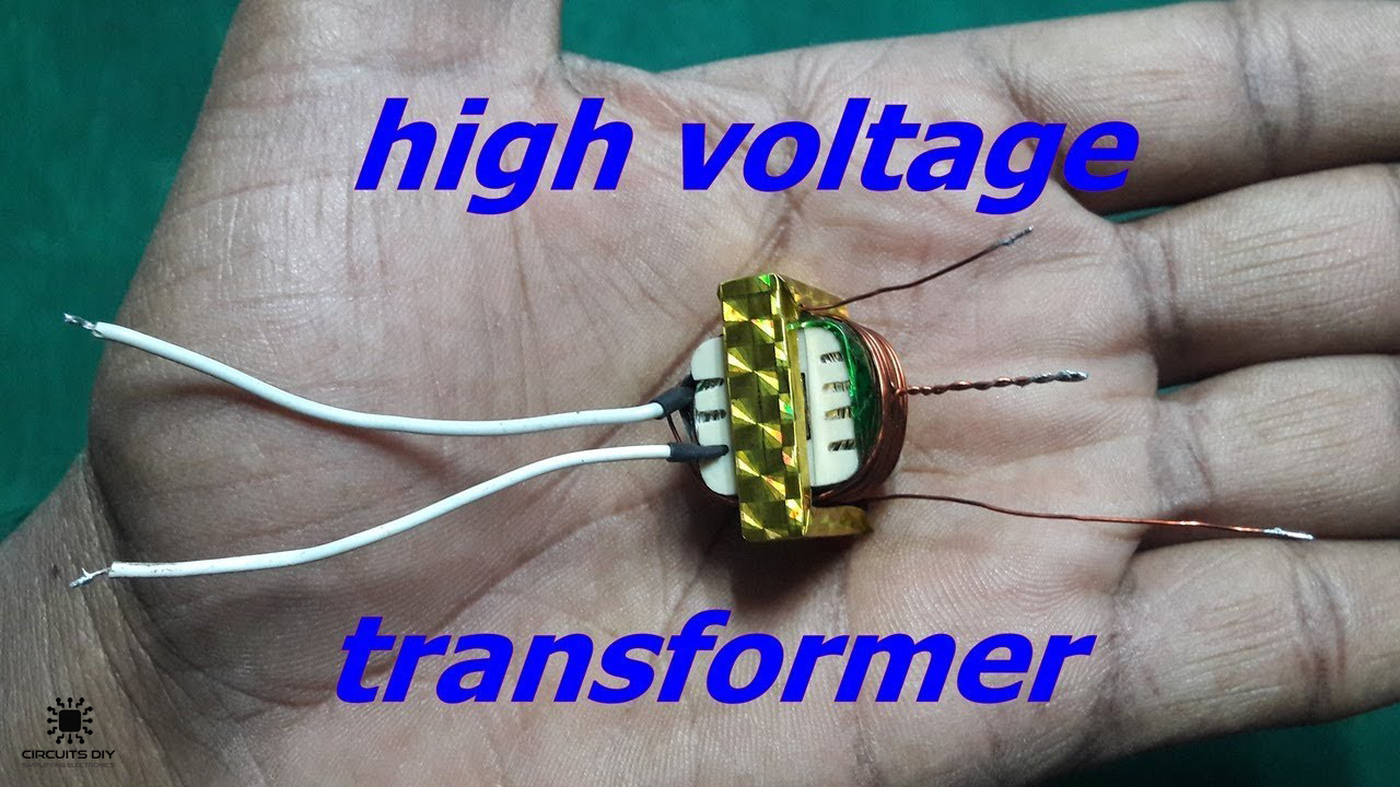
What is a High Voltage Transformer?
Would you like to learn how to make a high voltage transformer using a small no. of parts? High voltage transformers are an important part of the electrical & electronic industry with their uses seen in many industries. So, in this project, we will learn How To Make A High Voltage Transformer Using a 18650 Li-ion Battery.
A High voltage transformer converts voltages from one level or phase configuration to another, usually from lower to higher. They include features for electrical isolation, power distribution, and control and instrumentation applications. They are normally used in high voltage labs for testing purposes.
Hardware Component
The following components are required to make High Voltage Transformer Circuit
| S.No | Component | Value | Qty |
|---|---|---|---|
| 1. | 18650 Li-ion Battery | 3.7V | 1 |
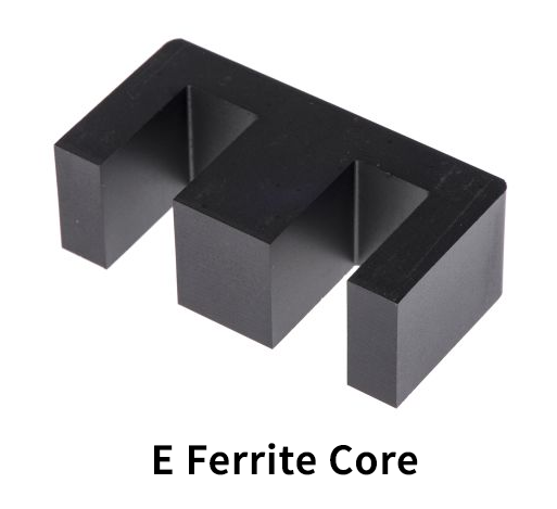
| 2. | E Core Ferrite Laminations | – | 1 |
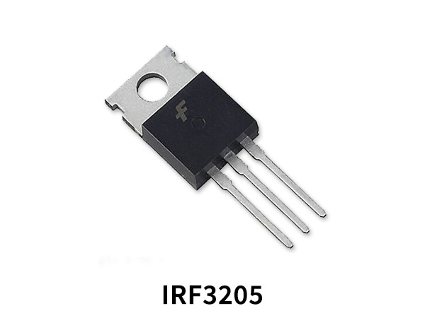
| 3. | N – Channel MOSFET | IRF3205 | |
| 4. | Enameled Copper wire | 38n. & 28n. | 1 |
| 5. | Wire sleeve | – | 1 |
| 6. | Lighter | – | 1 |
| 7. | insulating tape | – | 1 |
| 8. | Soldering Iron | 45W – 60W | 1 |
| 9. | Soldering wire & flux | – | 1 |
| 10. | Power Resistor | 220 Ohm/0.5W | 1 |
| 11. | Heatsink | – | 1 |
| 12. | Jumper wire | – | As per need |
IRF3205 Pinout
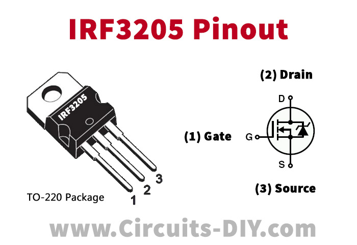
For a detailed description of pinout, dimension features, and specifications download the datasheet of IRF3205
E – Ferrite Core
Useful Steps
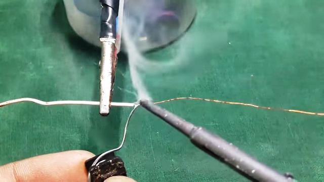
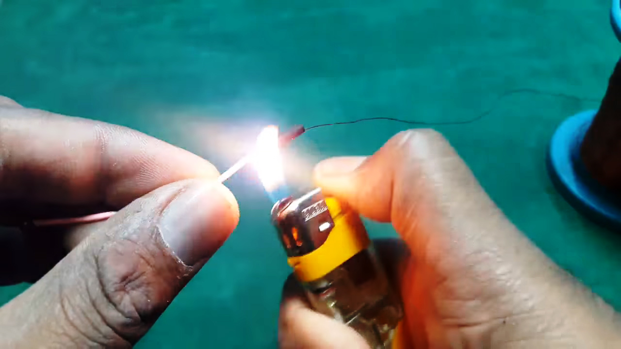
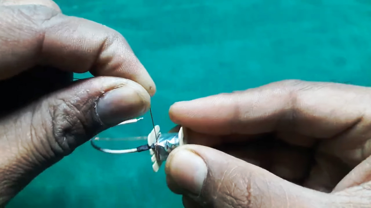
1) Solder a jumper wire with the sanded end of a 36n, enameled copper wire & cover the soldered joint with a wire sleeve.
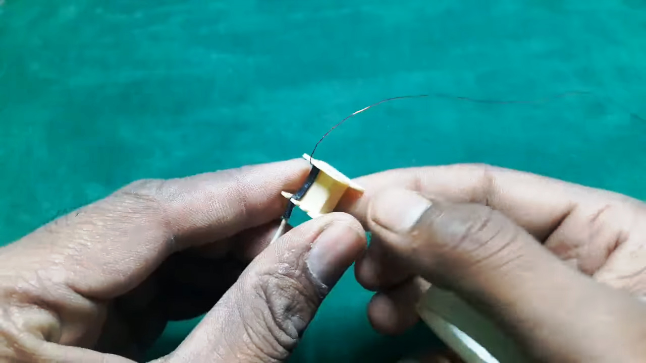
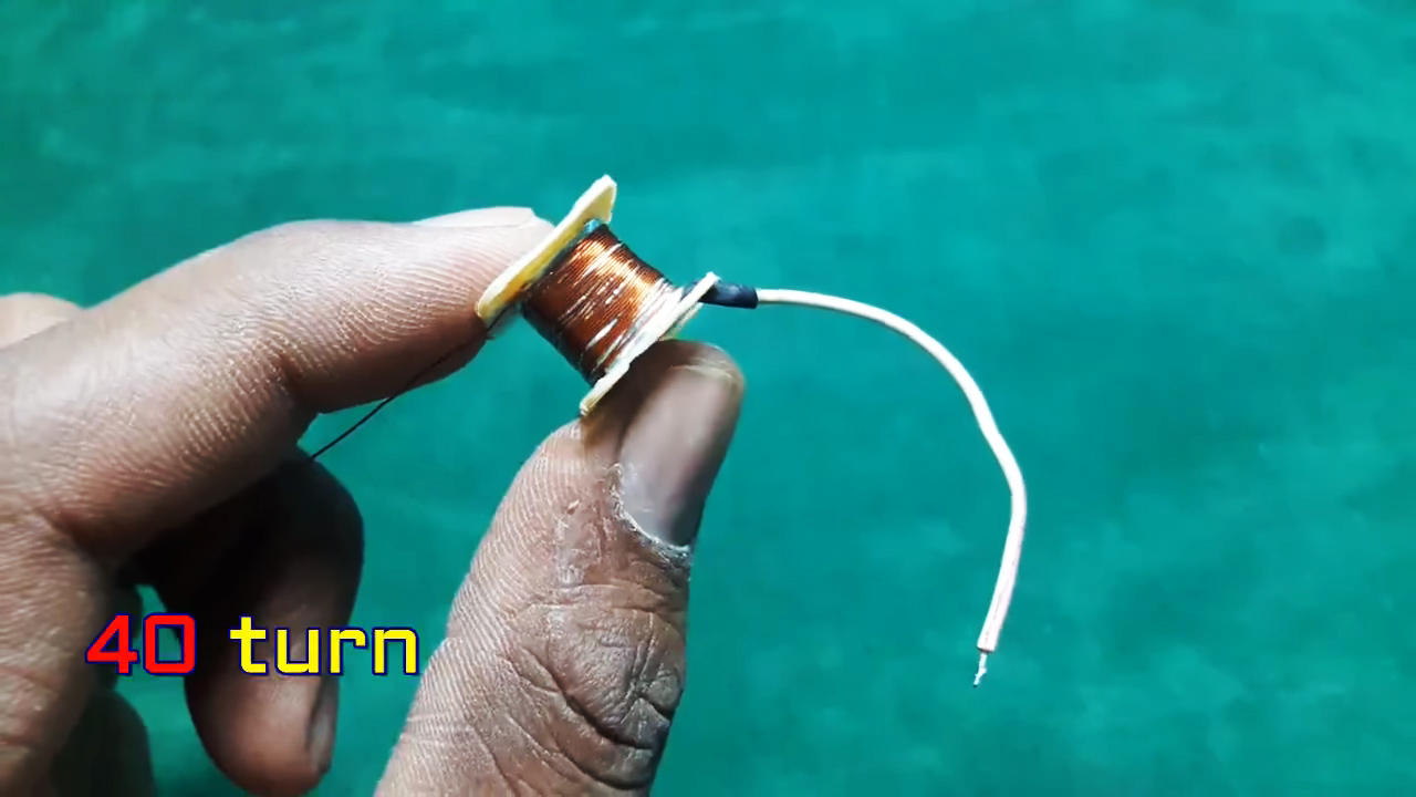
2) Stick the insulated wire sleeve into the ferrite core holder & wound the 38n. wire for 40 turns.
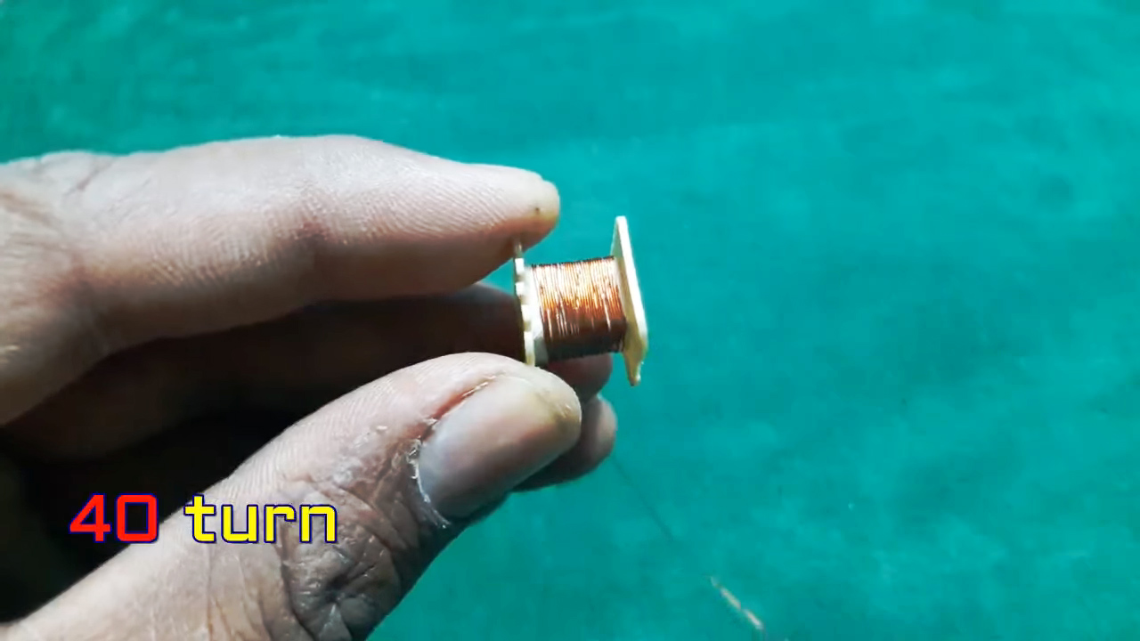
3) Cover the winding using insulated tape & wound another 40 turns. repeat the process till you have wounded 400 turns, isolating 40 turns per winding using tape.
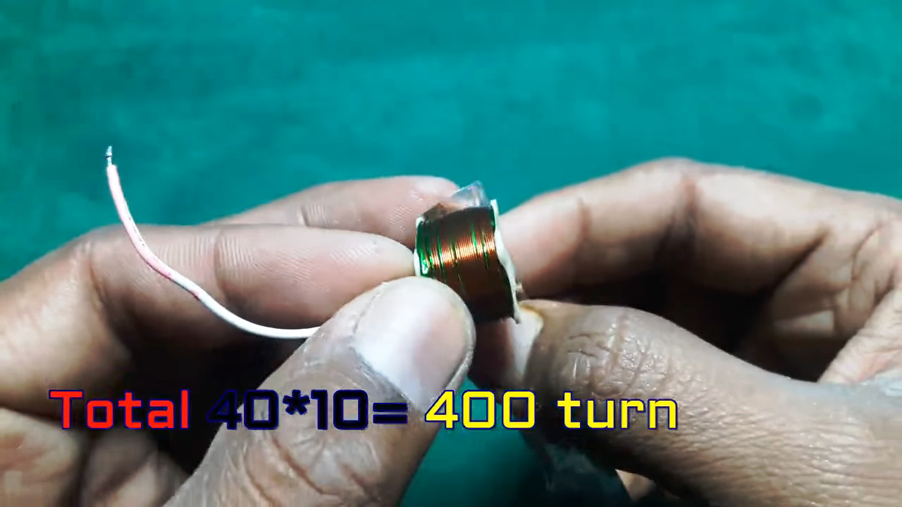
4) Solder connecting wires on another end of the winding.
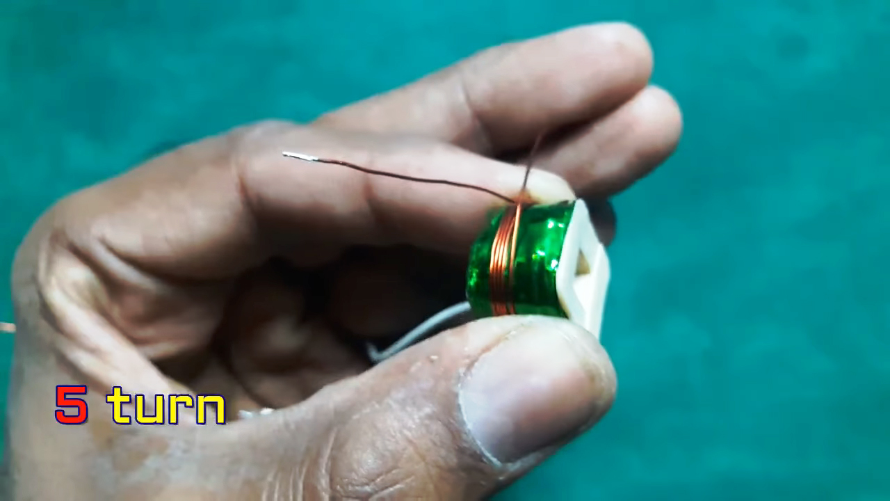
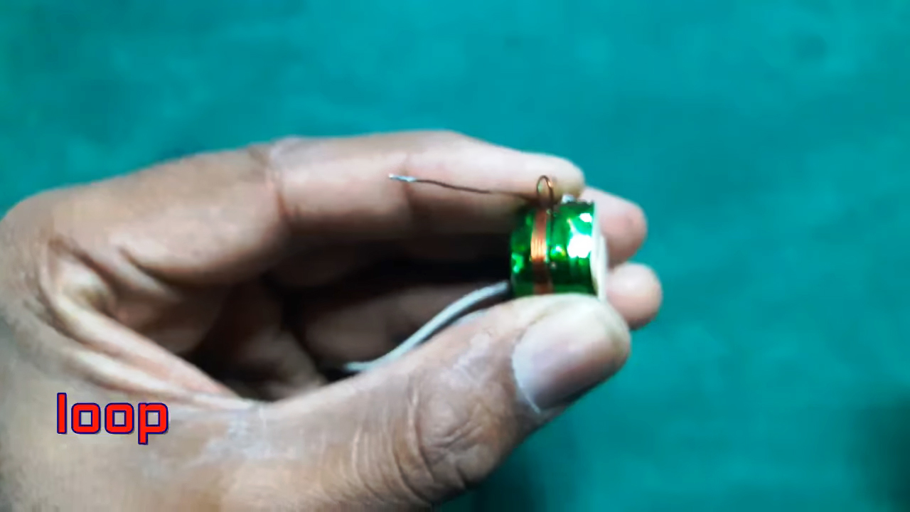
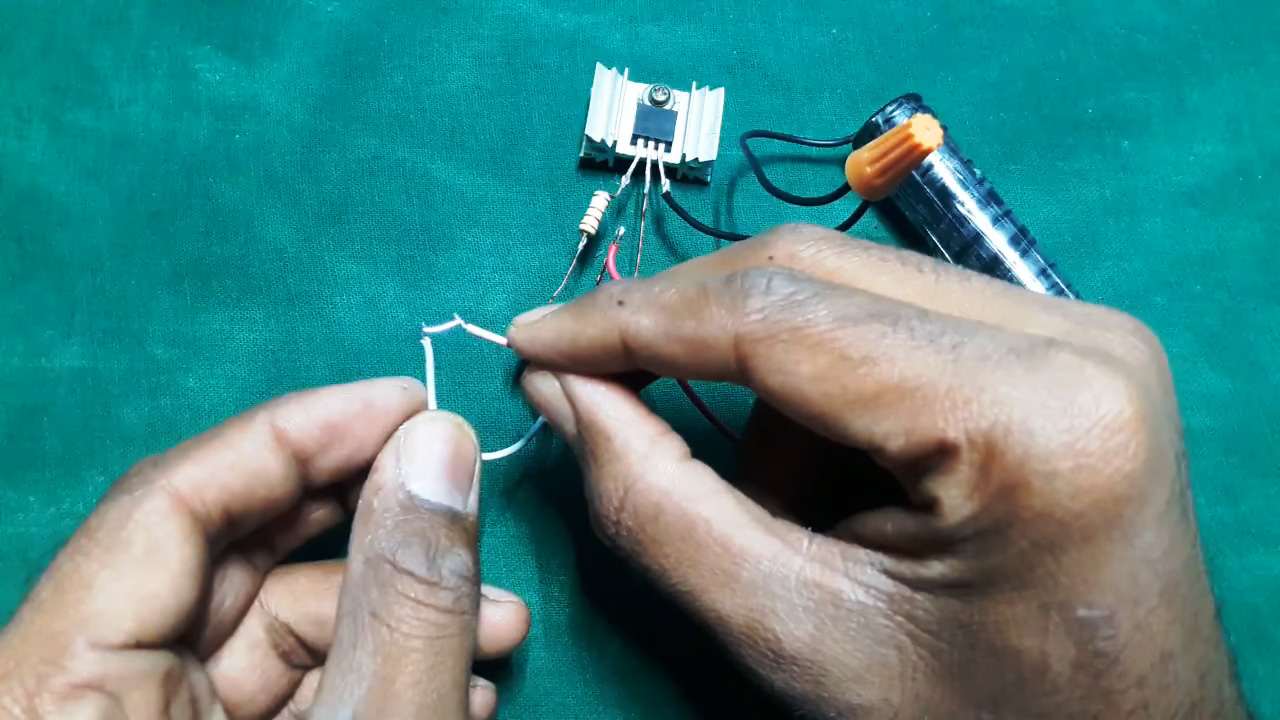
5) Now, using the 28n. enameled copper wire wound 5 turns, then wind a piece of wire loop out its outer end twisting into a terminal. Now wound 5 turns of 28n. enameled copper wire, this will result in a 5,0,5 terminal configuration.
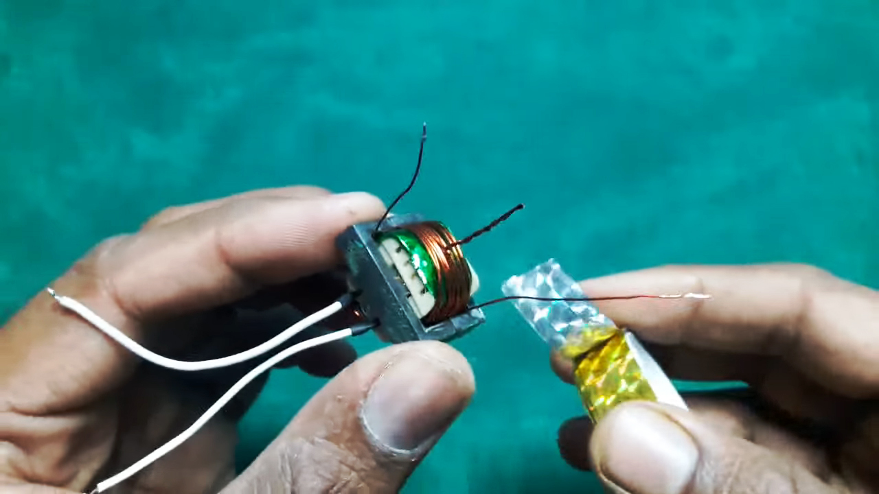
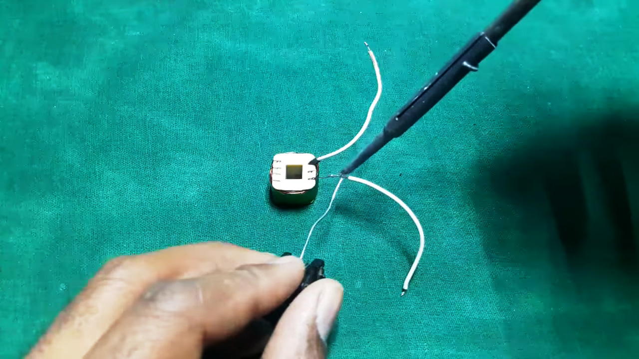
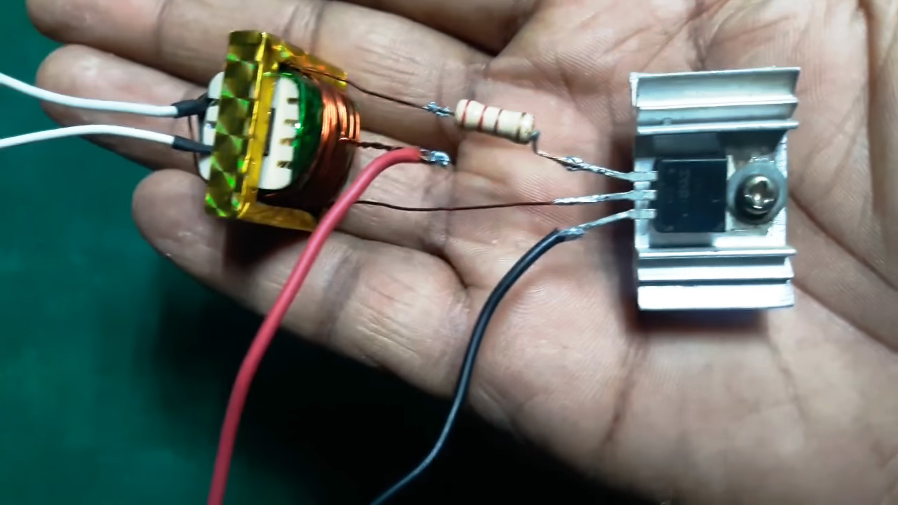
6) insulate the body of the E – ferrite core using insulating tape. After that connect a 220ohm power resistor to the primary of the transformer, solder a connecting wire to the middle terminal of the primary, joining to the +ve of the 18650 battery.
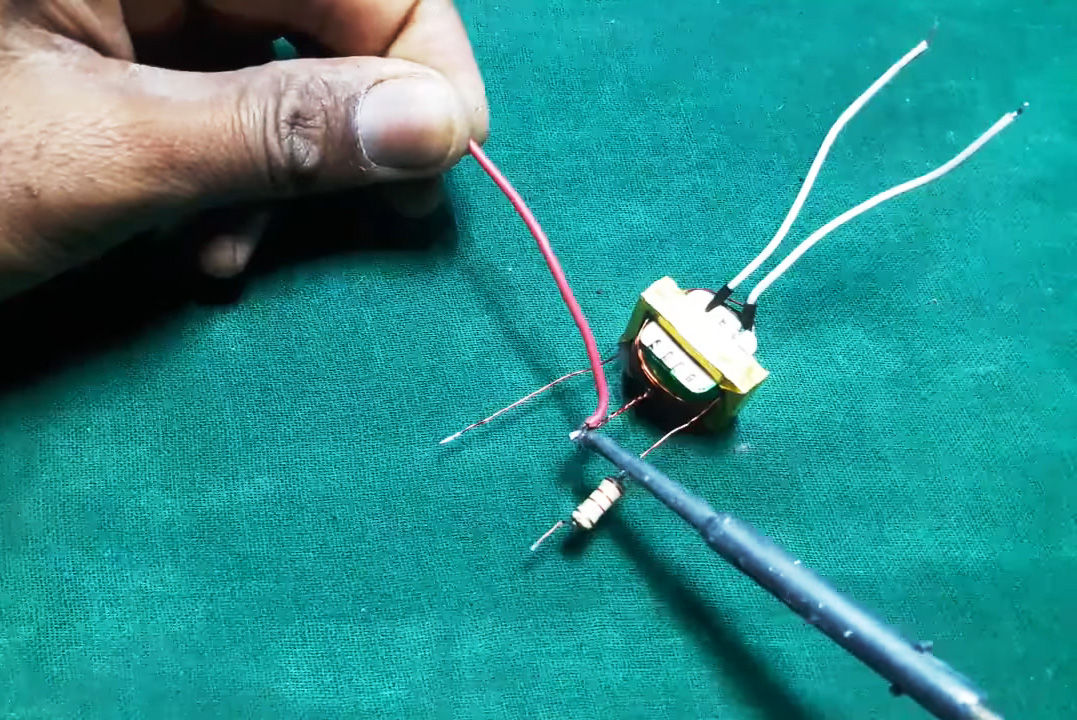
7) solder the resistor to the gate of the IRF3205, Drain to the primary of the transformer & the source to the -ve terminal of the 18650 battery.
8) Test the circuit.
Working Explanation
The working of this circuit is quite simple. A 3.7V DC input is taken from a 18650 DC Li-ion Battery. the output of the battery goes to the source of N-channel MOSFET (IRF3205). The IRF3205 can switch currents up to 110A and 55V, making it ideal to be used in this project.
The output from the MOSFET goes through enameled copper windings to an E – ferrite core, with a 220 Ohm resistor connected in series to the input of the ferrite core to mitigate the output voltage. The output of the ferrite core can range up from 110V to 150V and can be taken through appropriate jumper wires.
Applications
- It generally serves the purpose of a step-up transformer
Related posts:
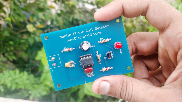 How to make a Simple Mobile Phone Call Detector Circuit
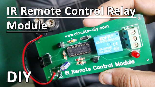 Infrared (IR) Remote Control Relay Module using TSOP1738 & CD4017
 Matrix Scrolling Weather Station & Clock
 Simple VU Meter Circuit using LM358 - Electronics Projects
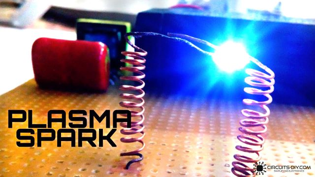 How To Create a Plasma Spark Generator Using a 4V DC Battery
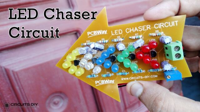 LED Chaser Circuit using Transistors - Electronics Projects


