The high / over temperature sensor or detector alarm is a circuit that senses the temperature of the circuit and activates the alarm and flashes the LED when the temperature rises above normal. Thermocouples or RTD (Resistance Temperature Detectors) are the components that are used in the circuit to measure temperature.

Hardware Components
The following components are required to make Temperature Sensor Alarm Circuit
| S.no | Component | Value | Qty |
|---|---|---|---|
| 1. | Resistors | 120K, 10K, 1K | 1, 1, 3 |
| 2. | Transistors | 2N4403, 2N4401 | 1, 1 |
| 3. | IC | NE555 Timer | 1 |
| 4. | Potentiometer | 1M, 100K | 1, 1 |
| 5. | DC power supply | – | 1 |
| 6. | Thermistor | 10K | 1 |
| 7. | LED | 5mm | 1 |
| 8. | Buzzer | – | 1 |
| 9. | Capacitors | 10uF, 0.01uF | 1,1 |
NE555 IC Pinout

For a detailed description of pinout, dimension features, and specifications download the datasheet of 555 Timer
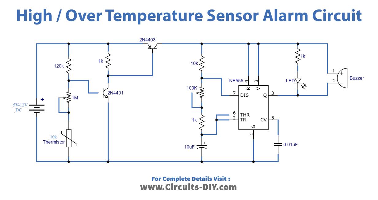
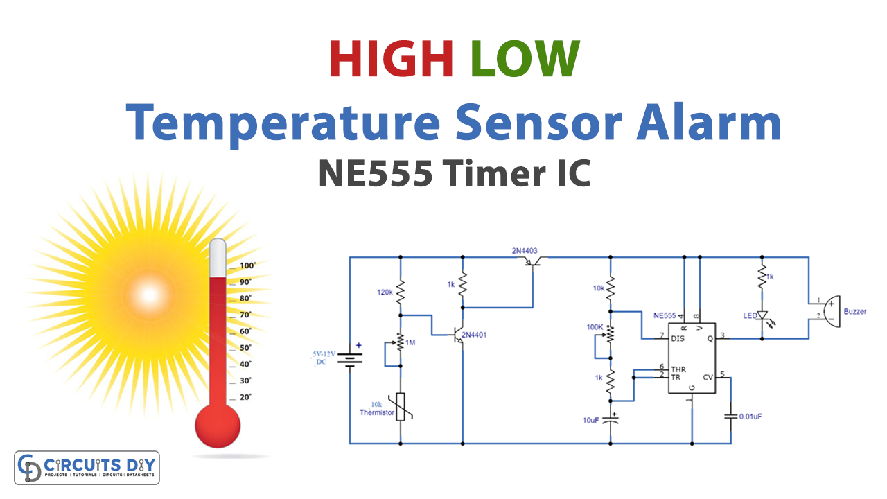
Temperature Sensor Alarm Circuit

Working Explanation
This circuit can run from 5V to 12V DC. For temperature sensing, a 10 K NTC thermistor is used, the temperature point at which you want to trigger the buzzer can be chosen using the 1 M variable resistance. When the temperature around the thermistor rises above the preset point, the circuit will trigger an alarm and flashes an LED. The buzzer and LED’s beeping and blinking rate can be controlled using the 100 K variable resistor connected via the 1 K resistor between pin6 & 7 of the 555 IC. There are two transistors, one NE555 IC, a buzzer are also connected to the circuit.
Application and Uses
- It is used as a sensor to prevent high/over-temperature in the circuit.


