Introduction
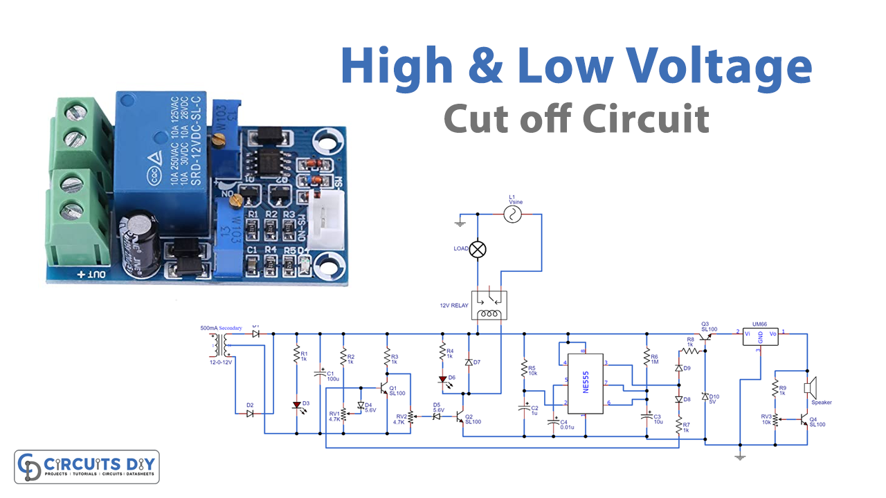
In electronics, both voltages and under voltages can harm and damage the devices. Especially, high voltages are also harmful to the environment. So, in the case of high and low voltage, the particular device needs a cut-off circuit. Therefore, this high and low voltage cut-off circuit with delay and alarm can protect devices. Like it ensures the safety of air conditions, refrigerators, Televisions, etc. The circuit generates the sound when resuming the power.
The circuit is lower in cost as compared to the other voltage stabilizers. And, it consumes less power. Therefore, rather than that stabilizers, it is better to use this circuit to control the devices. In addition, to assemble this circuit autotransformer is required. The output of the autotransformer will be connected to the primary side of the transformer. Most importantly, set that autotransformer to 160V.
Hardware Required
| S.no | Component | Value | Qty |
|---|---|---|---|
| 1 | IC | UM66 | 1 |
| 2 | Resistor | 1K, 10K, 1M | 7, 1, 1 |
| 3 | Potentiometers | 4.7K, 10K | 2, 1 |
| 4 | Diodes | 1N4001 | 5 |
| 5 | Electrolytic Capacitor | 100uF, 10uF, 1uF | 1, 1, 1 |
| 6 | Ceramic Capacitor | 0.01uF | 1 |
| 7 | Transistor | SL100 | 4 |
| 8 | IC | NE555 Timer | 1 |
| 9 | Speaker | – | 1 |
| 10 | Relay | 12V | 1 |
| 11 | Center Tapped Transformer | 12-0-12V, 500mA | 1 |
| 12 | Zener Diode | 5V, 5.6V | 1, 2 |
| 13 | LED | 2 |
Circuit Diagram
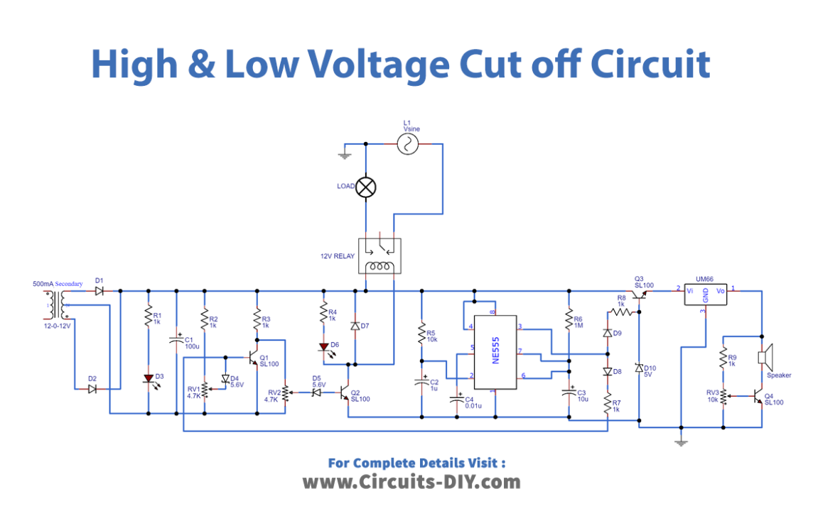
Working Explanation
When the voltages get higher. The transistor R1 starts conducting because of the diode D4. Meanwhile, transistor T2 will not conduct which turned OFF the relay. In the same vein when the voltage is lower. Both the transistors T1 and T3 will not conduct. And, this also deactivates the relay. When the power resumes negative voltage cones at NE555 IC, which is working as a stable multivibrator. This turns On the transistor T3. This T3 drives the speaker. As a result, the speaker beeps to indicate that power has resumed.
Application and Uses
- Stabilizers
- To cut-of high and low voltages voltage of any equipment


