The Heartbeat Sensor is used to measure the functions of the heart like heart rate (speed of the heart) body temperature & blood pressure. Today, Heartbeat Sensors are not only used in medical-related devices but also in some expensive smartphones to detect the heart beating rate.
In this tutorial, we are going to make the Heartbeat Sensor Circuit step by step. So, let’s start with the initial steps by watching this video:

PCBWay commits to meeting the needs of its customers from different industries in terms of quality, delivery, cost-effectiveness, and any other demanding requests. As one of the most experienced PCB manufacturers in China. They pride themselves to be your best business partners as well as good friends in every aspect of your PCB needs.
Hardware Components
The following components are required to make Heartbeat Sensor Circuit
| S. No | Component | Value | Qty |
|---|---|---|---|
| 1. | PCB | – | 1 |
| 2. | IC | LM358 | 1 |
| 3. | IR LED Pair | – | 1 |
| 4. | LED | 5mm | 1 |
| 5. | Ceramic Capacitor | 100nF | 1 |
| 6. | Electrolytic Capacitor | 4.7uF | 1 |
| 7. | Resistors | 220 ohm, 10K, 680K, 6.8K, 47K | 2, 1, 1, 1, 1 |
| 8. | Battery | 9v | 1 |
Useful Steps
Follow all steps carefully from the video tutorial above this post (Highly Recommended).
- First solder LM358 IC then
- Sold all LEDs
- Then all Capacitors
- Solder all Resistors
- Solder 9v battery connector
Finally , power up the circuit and test it.
LM358 Pinout
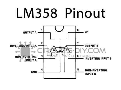
For a detailed description of pinout, dimension features, and specifications download the datasheet of LM358
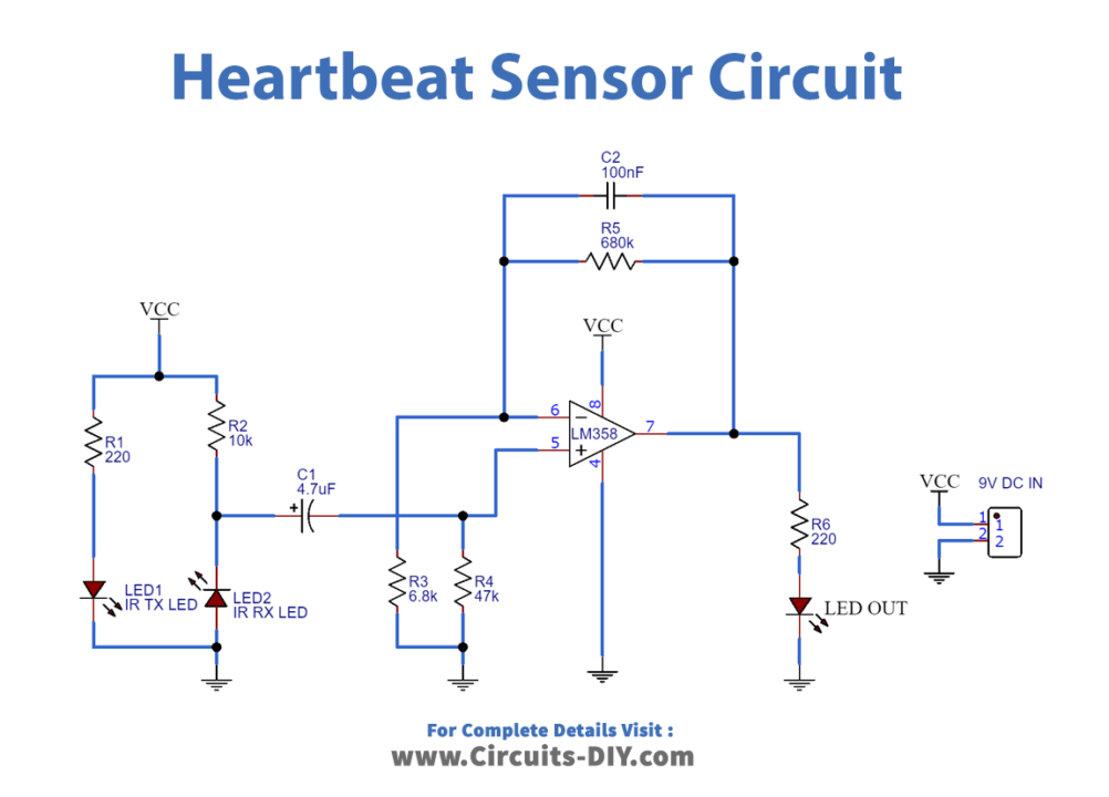
Circuit Diagram