What is a Heart Rate Monitor?
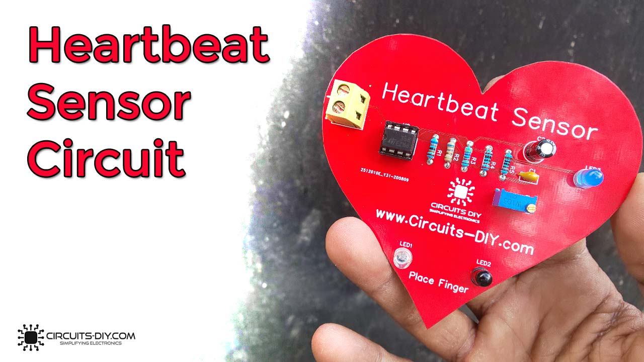
A Heart rate monitor is a simple electronic circuit that monitors the user’s heartbeat by indicating the changes in blood volume through any organ of the body which causes a change in the light intensity through that organ. They serve as an important part of today’s the health care industry & function as a vital heart rate measurement device for people with different ailments such as hypertension, arrhythmia & other metabolic syndromes. So, in today’s article, we will go over a step-by-step process on how to design a Heart rate monitor using LM358 Op-Amp IC.
This heart rate monitor circuit functions on the principle of photographically: The change in the volume of blood in any organ causes a change in the light intensity through that organ. Here, A Light from an LED will be transmitted through any region of the body such as a finger, and will then be received by an IR receiver.
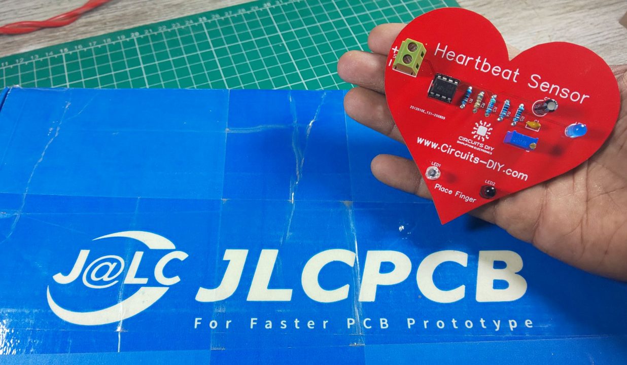
JLCPCB is the foremost PCB prototype & manufacturing company in china, providing us with the best service we have ever experienced regarding (Quality, Price Service & Time).
Hardware Components
The following components are required to make Heart Rate Monitor Circuit
| S.no | Component | Value | Qty |
|---|---|---|---|
| 1. | Opamp IC | LM358 | 1 |
| 2. | IR LED | 5mm | 1 |
| 3. | IR Receiver (Photodiode) | – | 1 |
| 4. | LED | 5mm/3.5V | 1 |
| 5. | Capacitors | 47uF, 100nF | 1 |
| 6. | Resistors | 47K, 680K, 6.8K, 220 Ohms | 1 |
| 7. | Soldering Iron | 45W – 65W | 1 |
| 8. | Variable Resistor | 10K | 1 |
| 9. | DC Battery | 9V | 1 |
| 10. | Veroboard | – | 1 |
| 11. | Battery clip | – | 1 |
| 12. | Jumper wires | – | As per need |
LM358 Pinout

For a detailed description of pinout, dimension features, and specifications download the datasheet of LM358
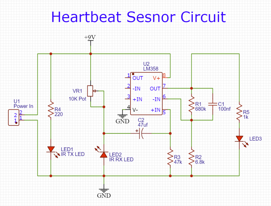
Heart Rate Monitor Circuit
Working Explanation
The working of this circuit is actually pretty simple. On placing the left-hand finger on the IR transceiver junction, the IR rays reflect through as per the volume of blood in the blood vessels & capillaries. The reflected light is then received on the IR photodiode, sending an input control signal to the non-inverting input pin 5 of the Op-amp IC. The LM358 IC amplifies the input signal & triggers the LED to blink. You can use a 9V battery to power this project.
Applications
- Usually used to measure exercise intensity of any training sessions.
- Also used in hospitals to measure & monitor the heartbeat pulse of patients.


