
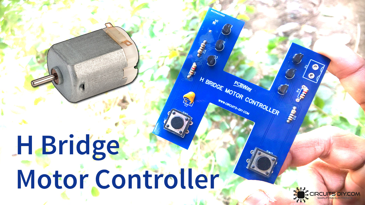
The directional control of a DC motor is the intentional change of certain DC motor drive factors that govern the rotational direction of the DC motor shaft. When dealing with practical electronics in an industrial or academic setting, there are many instances where directional control of a DC motor is required. An example would be an assembly line conveyor belt, normally used for inspection in almost every production industry. Such conveyor systems require bidirectional motor control in order to perform inspections with the utmost accuracy. In today’s tutorial, we are going to go over a step by step procedure on how To Make an H Bridge Motor driver circuit using NPN & PNP transistors.
H Bridge Motor Driver
An H Bridge motor driver circuit allows a voltage to be applied across a load in any direction. It is fabricated by using four switching devices (transistors/MOSFETS). H-bridge circuits are frequently used in robotics and many other applications to allow DC motors to run forward & backward. H Bridge motor controller circuits are also used in different converters such as DC – DC, DC – AC, AC – AC converters
PCBWay commits to meeting the needs of its customers from different industries in terms of quality, delivery, cost-effectiveness, and any other demanding requests. As one of the most experienced PCB manufacturers in China. They pride themselves to be your best business partners as well as good friends in every aspect of your PCB needs.
Hardware Components
The following components are required to make H Bridge Motor Driver Circuit
| S.no | Component | Value | Qty |
|---|---|---|---|
| 1. | DC Motor | 12V/60000 RPM | 1 |
| 2. | Transistor | BC547, BC557 | 2, 4 |
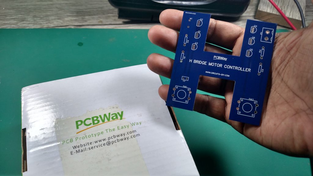
| 3. | H-Bridge PCB | PCBWay | 4 |
| 4. | Ceramic Capacitor | 100nf | 1 |
| 5. | Resistors | 100 Ohm,1k | 4 |
| 6. | Battery with Clip | 9V | 1 |
BC547 Pinout

For a detailed description of pinout, dimension features, and specifications download the datasheet of BC547
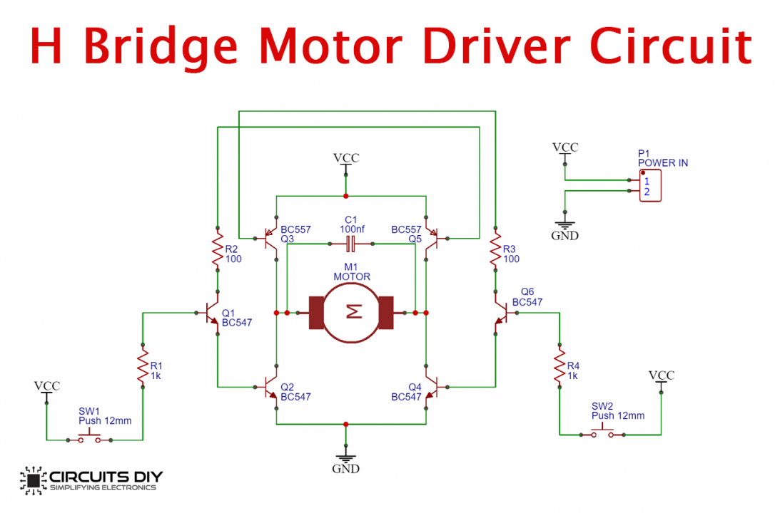
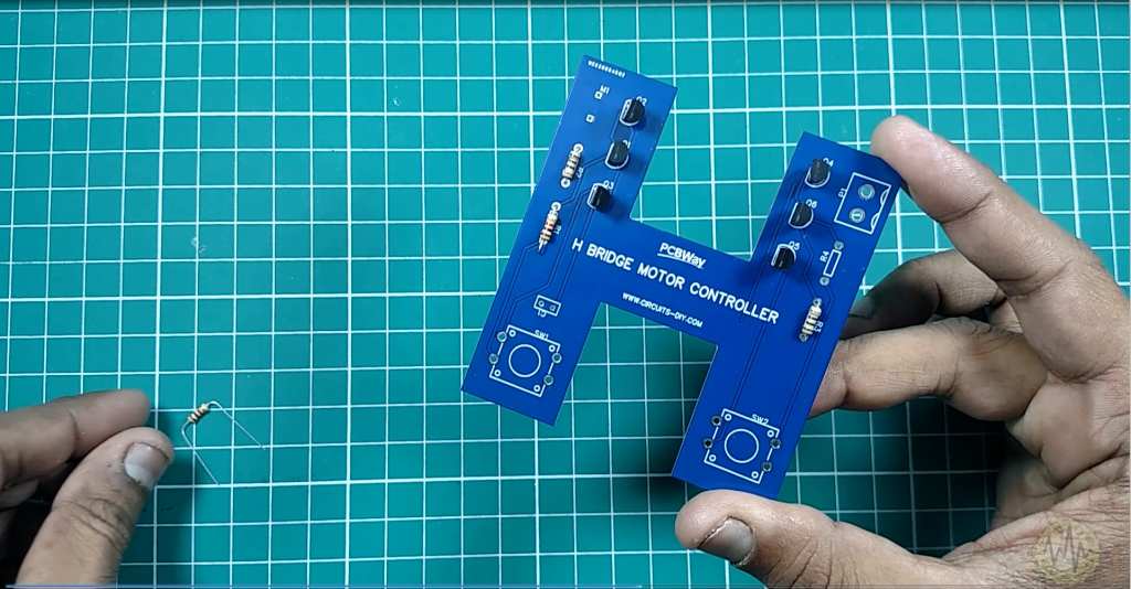
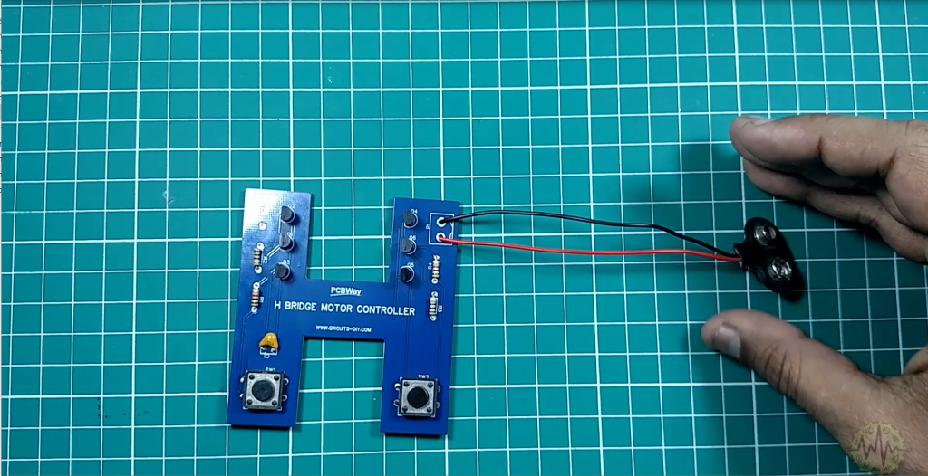
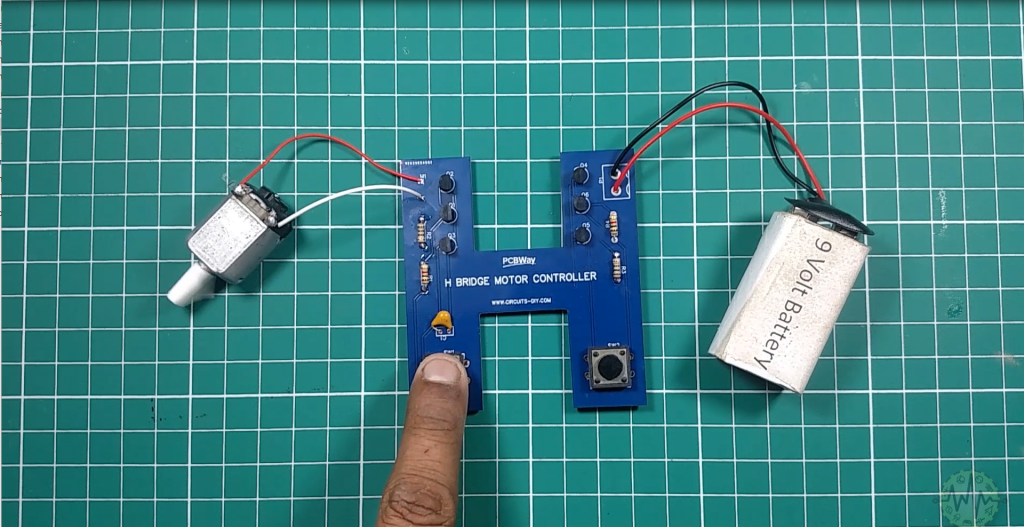
H Bridge Motor Driver Circuit
Useful Steps
Follow All Steps Carefully from the Video Tutorial Above (Recommended)
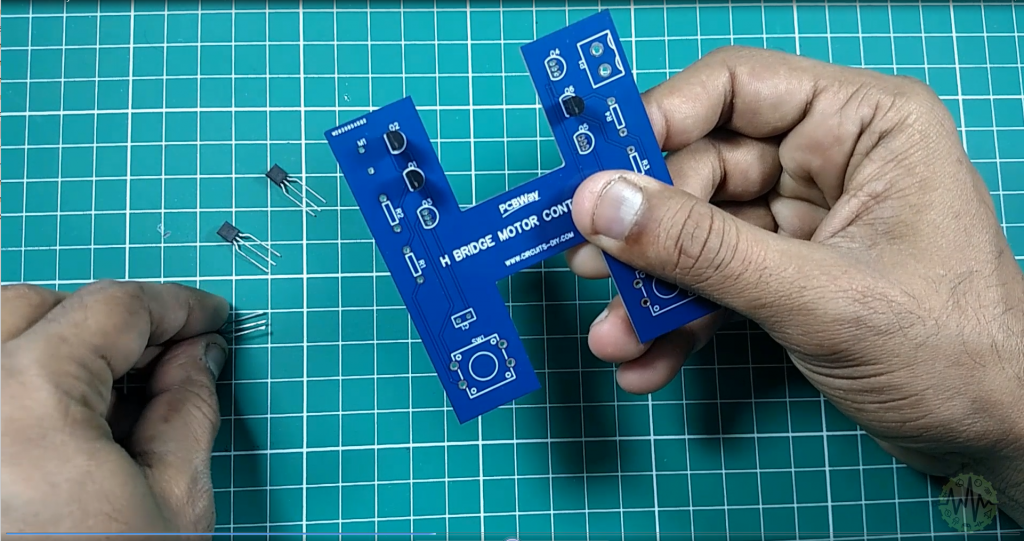
1) Solder All Transistors
2) Solder All Resistors
3) Solder Ceramic Capacitor
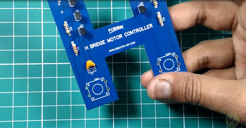
4) Solder Push Buttons
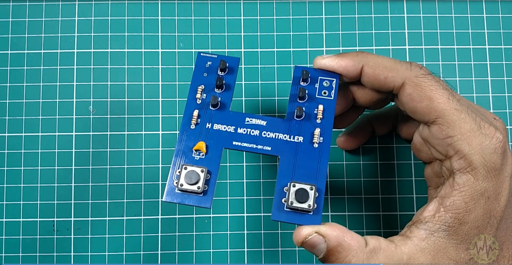
5) Solder Power Connector
6) Solder DC Motor Input Wires
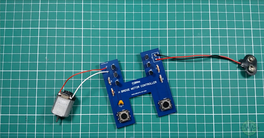
7) Let’s Power up the Circuit
Working Explanation
The working of this H-bridge circuit is as following, Resistors R1 to R4 limit the base current of their corresponding transistors. On completing the circuit & pressing the pushbutton SW1, transistors Q3 and Q4 will be on and current passes through the motor from left to right and the motor start its rotation in the respective direction.
On pressing the pushbutton SW2, transistors Q5 and Q2 will be on and the current passes through the motor from right to right making the motor rotate in the opposite direction. You should never press both switches at the same time. Doing that will create a very low short resistance path between the Power and GND, effectively short circuiting your power supply. This condition is called ‘shoot through’ and is a sure fire way to quickly destroy your H-bridge.
Applications
- Usually used in devices such as servo motors, motor drivers, and AC/DC motors, etc.
- Also used in devices such as robots, servos, conveyors etc.
- Also used in controlling various drones used in applications such as surveillance of property & terrain navigation.
Related posts:
 LED Audio Level Meter Circuit Using 2N4401 Transistors
 How to make Automatic Night Light Sensor Project
 6 Tips to Reduce PCB Size for Your Projects
 Laser Tripwire Alarm Circuit Using NE556 Dual Timer IC
 Top 5 Best PCB Electronics Projects For Complete Beginners
 Forward Reverse DC Motor Control Diagram with Timer IC


