PWM (Pulse Width Modulation) is an essential feature of today’s microcontroller because of the need to control many devices in almost every field of Electronics. 555 Timer IC is a highly convenient and versatile IC that you can use in many applications. Here we will use a 555 timer IC for generating PWM.
Pulse Width Modulation is a digital signal most commonly used in control circuits. It sets this signal high (5V) and low (0V) within a predetermined time and speed. Signal remains high during the on-time and remains low during the off-time.

Hardware Components
The following components are required to make PWM Generator Circuit
| S.No | Component | Value | Qty |
|---|---|---|---|
| 1. | Breadboard | – | 1 |
| 2. | Battery | 9v | 1 |
| 3. | Connecting Wires | – | 1 |
| 4. | IC | NE555 Timer | 1 |
| 5. | Potentiometer | 10k | 1 |
| 6. | Resistors | 100 ohm,1k | 1, 1 |
| 7. | Ceramic Capacitor | 100nF | 1 |
| 8. | LED | 5mm | 1 |
| 9. | Multimeter | – | 1 |
| 10. | Diode | 1N4148 | 2 |
555 IC Pinout

For a detailed description of pinout, dimension features, and specifications download the datasheet of 555 Timer
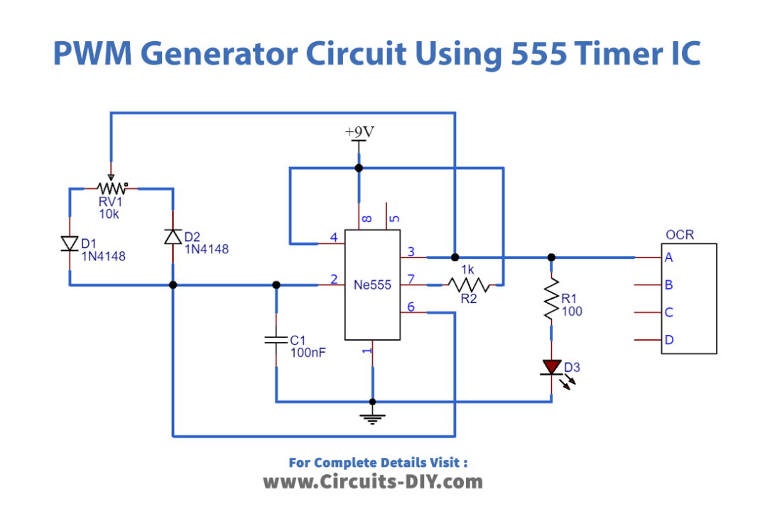
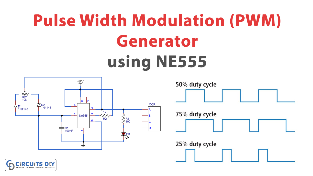
PWM Generator Circuit

Working Explanation
We have applied a variable resistor in place of fixed resistors to change the duty cycle of the output signal. Charging a capacitor through diode D1 and discharging through diode D2 will generate a PWM signal on the output pin of the 555 timers.
Application
We use PWM for motor controlling, lighting control, etc. At times we do not use a microcontroller in our applications. If we desire to make PWM without a microcontroller, then we go for some general-purpose ICs like op-amp, timers, pulse generators, etc.


can you tell us at which frequency this circuit is working at
Thanks
You can tune it to any 1khz to 1mhz