Introduction
Many adults, especially parents, complain that kids always open the fridge every time they pass by it. Thus, they want something that keeps them away. Like the regular Door alarms, which are an excellent way to keep your home safe from intruders, this fridge door alarm circuit is a perfect way to keep your refrigerator safe from children. So, together with us, let’s make this a fun project. The Project requires fundamental electronic components readily available in the market.
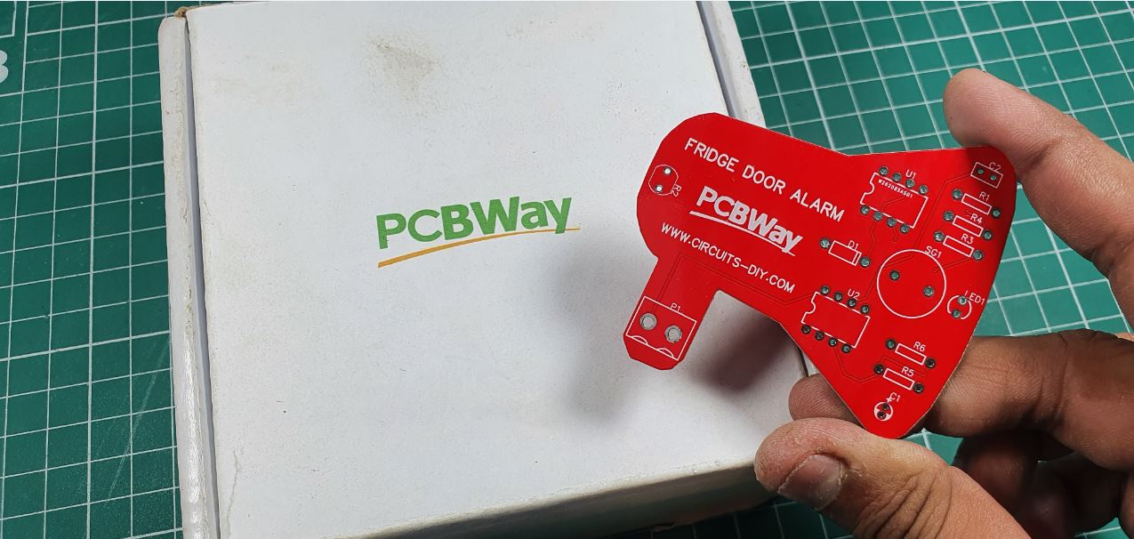
PCBWay commits to meeting the needs of its customers from different industries in terms of quality, delivery, cost-effectiveness, and any other demanding requests. As one of the most experienced PCB manufacturers in China. They pride themselves to be your best business partners as well as good friends in every aspect of your PCB needs.
Hardware Components
The following components are required to make Fridge Door Alarm Circuit
| S.no | Component | Value | Qty |
|---|---|---|---|
| 1. | IC | NE555 timer | 2 |
| 2. | Resistor | 100 ohms, 10K, 100K, 470K | 1, 1, 1, 2 |
| 3. | Capacitor | 47uf | 1 |
| 4. | Diodes | 1N4007 | 1 |
| 5. | LED | – | 1 |
| 6. | Buzzer | – | 1 |
| 7. | Power supply | – | 1 |
| 8. | LDR | – | 1 |
NE555 IC Pinout

For a detailed description of pinout, dimension features, and specifications download the datasheet of 555 Timer
Fridge Door Alarm Circuit
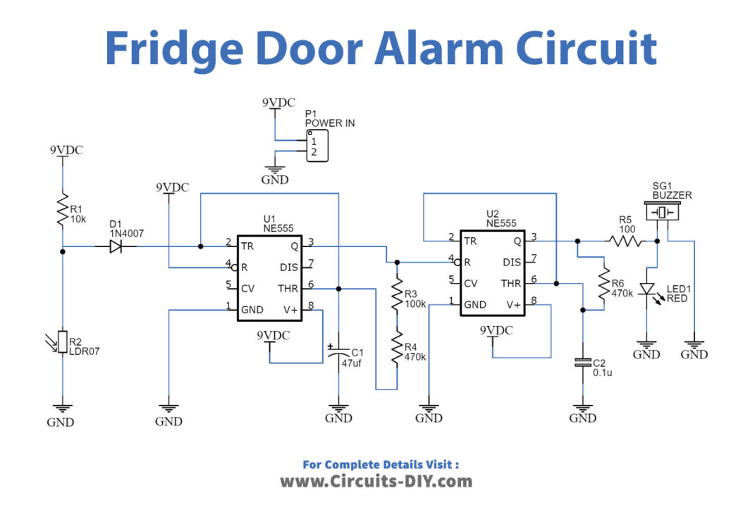
Working Explanation
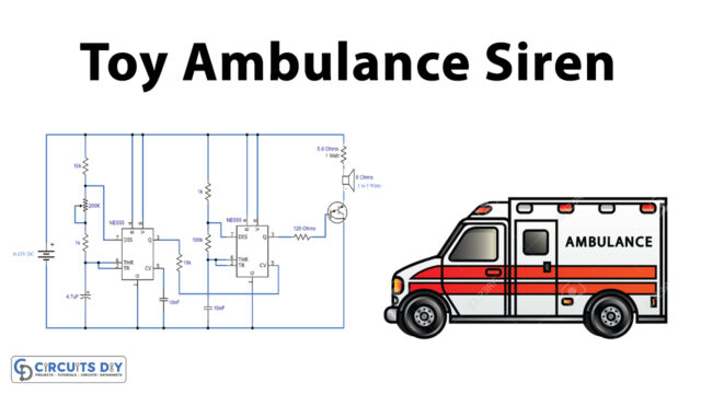
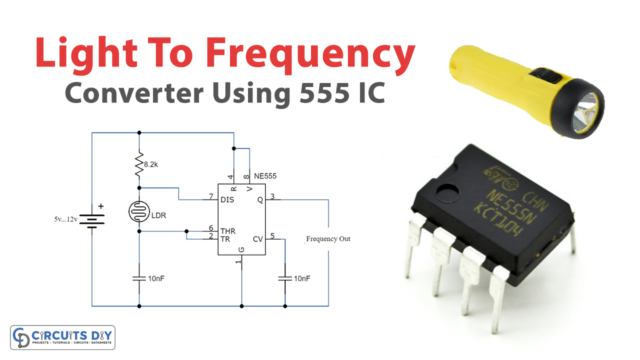
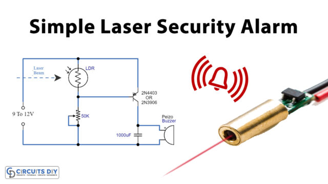
The LDR is used in this fridge door alarm circuit as the primary component and two 555 timer ICs. As we know, the fridge has a light in it, which turns On when we open the refrigerator. Here the LDR plays the role. Since ita a light-dependent resistor, when the fridge is closed, the LDR provides high resistance and maintains the resistor R1 fully charged. The potential divider’s output voltage appears across the capacitor greater than 2/3Vcc, making the output LOW.
When we open the fridge, light falls on the LDR, lowering its resistance and causing the capacitor to discharge; then, the output begins to oscillate at a particular frequency, and the result is HIGH. The capacitor charges once more and reaches a threshold before being discharged (this will continue until the LDR resistance reaches a critical level, which will occur in the absence of light).
This causes the second 555 timer to oscillate, leading the buzzer connected to the output and beep in a pattern that combines the oscillations of both the timers.
Application and Uses
- Inside the refrigerator circuits.