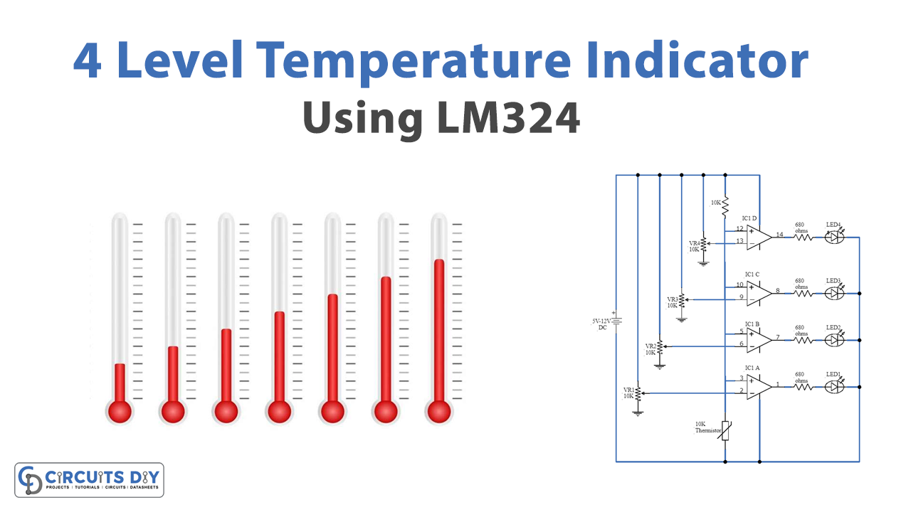
The four-level temperature indicator is a circuit that represents different temperature levels through the lighting of four different LEDs. The project involves the IC LM324 as its main component.
Hardware Required
| S.no | Component | Value | Qty |
|---|---|---|---|
| 1. | DC Battery | 5V-12V | 1 |
| 2. | Thermistor | 10KΩ | 1 |
| 3. | IC | LM324 | 4 |
| 4. | Variable Resistor | 10KΩ | 4 |
| 5. | Resistors | 680Ω 10KΩ | 4 1 |
| 6. | LEDs | – | 4 |
IC LM324
Pin Configuration
IC LM324 is a 14 dip low-cost, quad operational amplifier.

| PIN No | PIN Label | Description |
|---|---|---|
| 1 | Output 1 | Operational amplifier 1 output |
| 2 | – Input 1 | Inverting input of operational amplifier 1 |
| 3 | + Input 1 | Non-Inverting input of operational amplifier 1 |
| 4 | Vcc | Positive supply |
| 5 | + Input 2 | Non-Inverting input of operational amplifier 2 |
| 6 | – Input 2 | Inverting input of operational amplifier 2 |
| 7 | Output 2 | Operational amplifier 2 output |
| 8 | Output 3 | Operational amplifier 3 output |
| 9 | – Input 3 | Inverting input of operational amplifier 3 |
| 10 | + Input 3 | Non-Inverting input of operational amplifier 3 |
| 11 | Gnd | Negative supply |
| 12 | + Input 4 | Non-Inverting input of operational amplifier 4 |
| 13 | – Input 4 | Inverting input of operational amplifier 4 |
| 14 | Output 4 | Operational amplifier 4 output |
Features
- Integration of four operational amplifiers in a single package
- Low current drain
- Operating temperature: 0°C to 70°C
- Wide range of power Supply: 3V to 32V
Circuit Diagram

Explanation
The circuit is built around IC LM324, some resistors and variable resistors, and LEDs as indicators. IC LM324 is quad operational amplifier. Moreover, this circuit involves functioning of all the four operational amplifiers of the IC LM324 but each using a separate IC. Furthermore, with the adjustment of 10KΩ variable resistor attached with each of the IC, LEDs are able to indicate four different level of temperatures. Also, the resistor of value 680Ω is to limit the current flowing through LEDs.
Working is such that thermistor detects the temperature in the surrounding/room and, thus, sends signal to all the four ICs. The operational ICs are working in comparator mode. Hence, all four ICs amplifies and compare the signal with its pre-set variable resistor value. Once the comparison is done, the IC corresponding the temperature range will light up the LED attached with it.
Application
Temperature detector of a motor or engine


