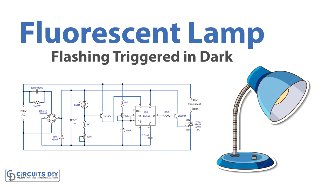
Fluorescent Lamp Flashing Triggered in the Dark is a night circuit to be precise. The circuit switches on during the night and turns off as soon as there is light in the morning. The circuit involves AC to DC conversion, light detection through LDR, and fluorescent light switching through IC NE555.
Hardware Required
| S.no | Component | Value | Qty |
|---|---|---|---|
| 1. | AC power supply | 230V | 1 |
| 2. | IC | NE555 Timer | 1 |
| 3. | Triac 8T44A | 400V/4A | 1 |
| 4. | Diode 1N4007 | – | 2 |
| 5. | Zener Diode | 12V/1W | 1 |
| 6. | LDR | – | 1 |
| 7. | NPN transistor | 2N3904 | 1 |
| 8. | PNP transistor | 2N3904 | 1 |
| 9. | Capacitor | 330nF/400V, 0.01µF | 1, 1 |
| 10. | Electrolytic capacitor | 330µF/25V, 10µF | 1 , 1 |
| 11. | Power Resistor | 1MΩ/1W | 1 |
| 12. | Resistor | 120Ω,330Ω,1KΩ,10KΩ | 1,1,1,1 |
| 13. | Variable resistor | 100KΩ | 2 |
| 14. | Fluorescent Lamp | 230V | 1 |
Circuit Diagram

Working Explanation
The circuit comprises three parts that are AC to DC conversion, then light detection, and finally turning ON/OFF of the lamp. The first part involves the conversion where a transformerless power down stepping is done. For this purpose, a power capacitor of 33nF/400V is used to step down the voltage, whereas, a full wave bridge rectifier made of diodes 1N4007 rectifies the signal. Furthermore, Zener Diode steps down the voltage to 12V for the IC to be operated. Since the circuit is in direct contact with the AC power supply, therefore extra care must be taken while handling the circuit.
Now, the second part involves the light detection part of the circuit. For this purpose, LDR in the circuit helps detect the darkness in the room or the surrounding area and further sends signals accordingly. The weak signal is then received by PNP transistor 2N3904 to amplify it. Moreover, a variable resistor of 100K is used to adjust the sensitivity of the circuit.
The third part involves the working of the IC NE555. The amplified signal is received through the input PIN 02 of the IC. Thus, the timer IC NE555 provides continuous square pulses to the NPN transistor 2N3904 to activate the switching mechanism. Thus, the NPN transistor starts its ON/OFF operation. At last, Triac 8T44A receives the switching signal from the NPN transistor. Triac is a three-terminal four-layer bidirectional semiconductor device that controls ac power in either direction. Hence, the fluorescent lamp of 230V lights up. As soon as the morning light shines on the LDR the work output changes accordingly and hence, the fluorescent lamp is turned off.
Application
- Visual indicator in dark
- Automation system


