Emergency products like tube lights and bulbs are becoming very popular as these become elegant solutions for situations where you can expect the AC power to go down sometimes from a few minutes to a few hours and you do not want the house to go into total darkness.
The emergency tube lights are powered by the alternating voltage source from a lighting circuit. And in the event of power cuts, the emergency light turns on and illuminates the surrounding area. Here we design a 20 watts fluorescent emergency light with a few simple components and a 12-volt 7Ah battery.
Hardware Required
| S.no | Component | Value | Qty |
|---|---|---|---|
| 1. | Step Down Transformer | 12-0-12V | 1 |
| 2. | Fluorescent Lamp | 20 watts | 1 |
| 3. | Transistor | 2N6101 | 1 |
| 4. | Resistor | 680Ω/3W | 1 |
| 5. | Variable Resistor | 2KΩ | 1 |
| 6. | Capacitor | 0.47uF/400V | 1 |
| 7. | Connecting Wires | – | – |
| 8. | Battery | 12V 7Ah | 1 |
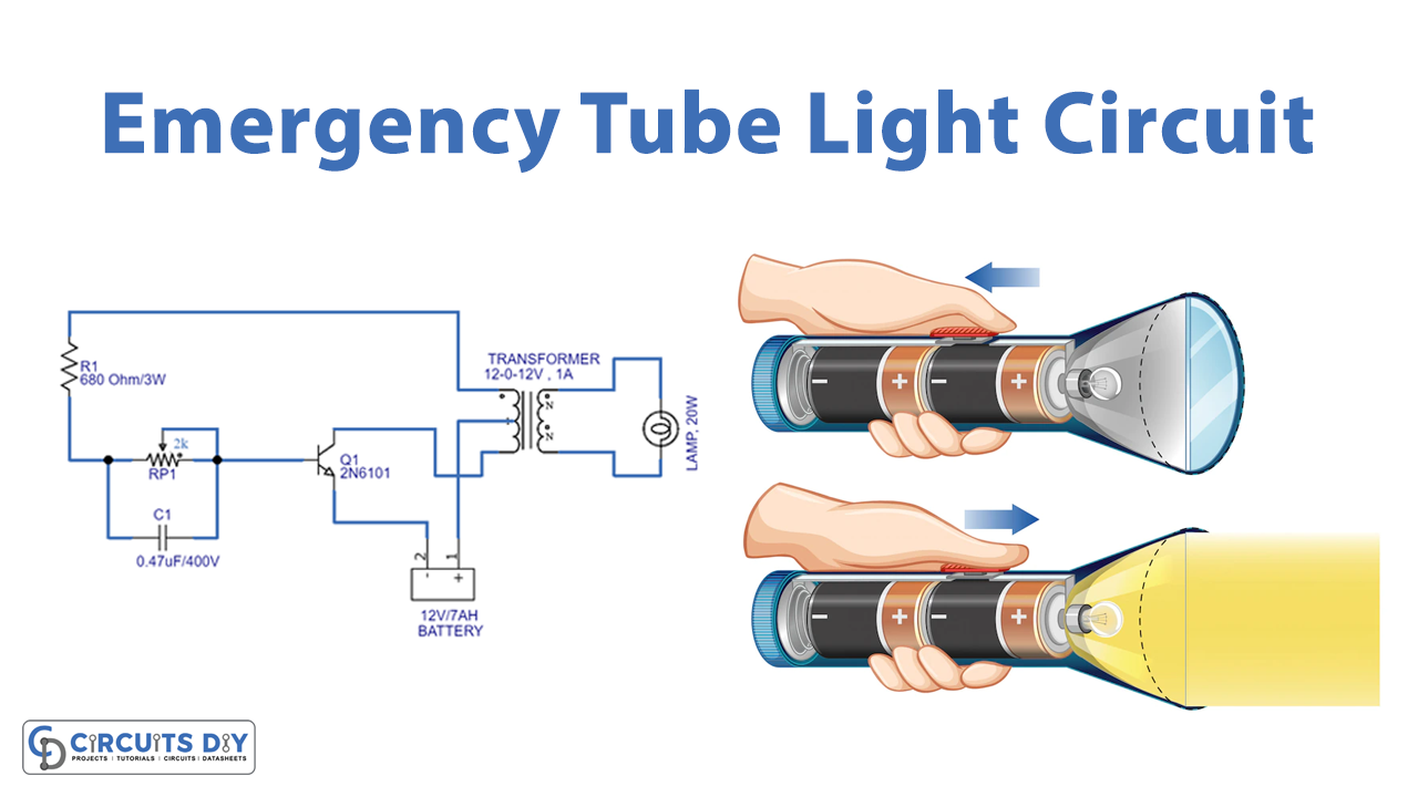
Circuit Diagram

Working Explanation
Here in this circuit transformer is the main part, this (12-0-12V) step-down transformer is utilized as the fluorescent driver transformer. The primary winding terminal is connected to the 20 watts fluorescent light and secondary (12-0-12V) center-tapped terminals are connected with a switching pulse circuit.
For the switching pulse here the VR1 variable resistor and C1 capacitor are placed, and the output from this circuit is applied to the switching power transistor Q1 2N6101. This transistor connects and disconnects the secondary winding of the transformer with the battery supply. Therefore it produces emf on winding, and this emf increases in primary winding (step up). Now the supply is enough to drive the 20 watts of fluorescent light.
Applications
- Can be used in night lamps, street lights, etc.
- The circuit is useful where there are load-shedding issues.
- Also, can be employed to avoid sudden power failures at workplaces.


