Electronic pianos are simple circuits that are usually seen in children’s toys & doorbells. These circuits produce a musical sound or beep on pressing a pushbutton. So, in this project, we are going to build a simple electronic piano using a 555 timer IC by following simple step-by-step instructions.
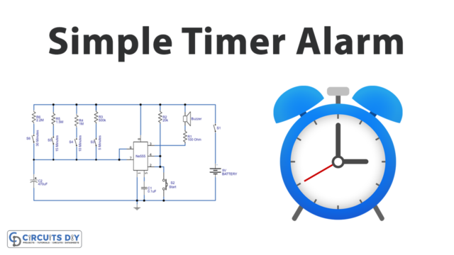
The heart of this Electronic Piano is a 555 timer operating in astable multivibrator mode. An astable multivibrator is a free-running oscillator that switches continuously between its two unstable states. With no external signal applied, the transistors alternately switch from cutoff to saturation state at a frequency that RC time constants of the coupling circuit determine. If these time constants are equal (R and C are equal) then a square wave will generate with a frequency of 1/1.4 RxC. Hence, an astable multivibrator is also a pulse generator or a square wave generator.
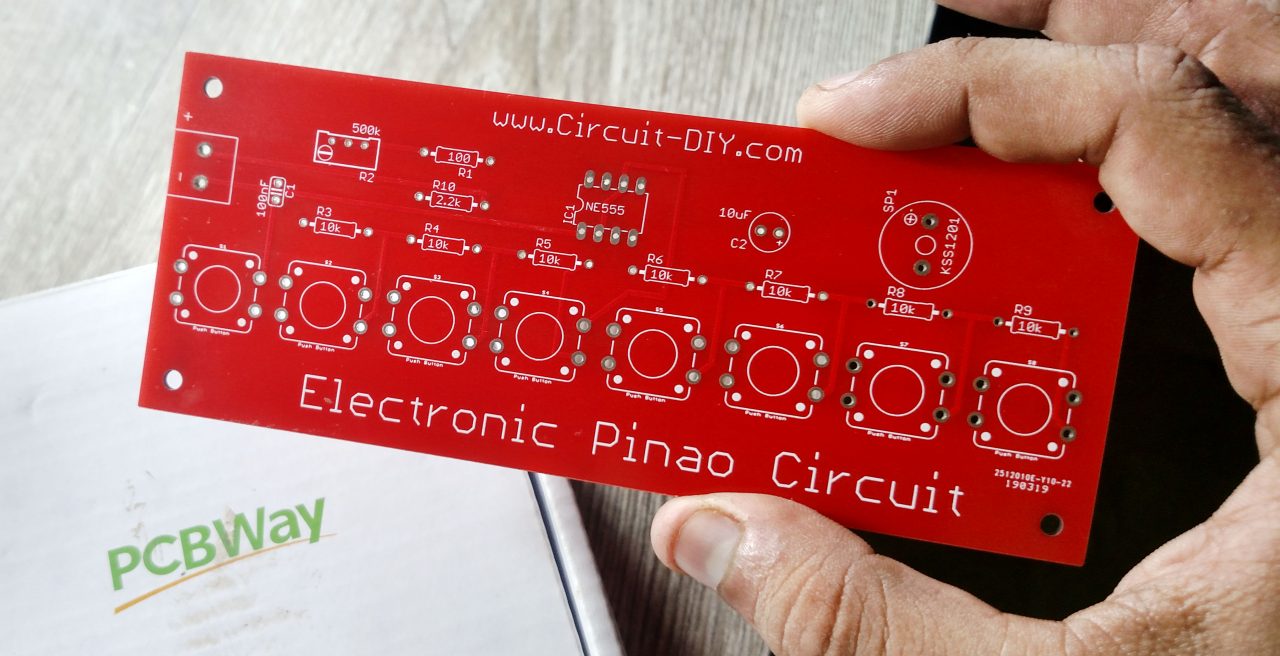
PCBWay commits to meeting the needs of its customers from different industries in terms of quality, delivery, cost-effectiveness, and any other demanding requests. As one of the most experienced PCB manufacturers in China. They pride themselves to be your best business partners as well as good friends in every aspect of your PCB needs.
Hardware Components
The following components are required to make Electronic Piano Circuit
[inaritcle_1]NE555 Pinout

For a detailed description of pinout, dimension features, and specifications download the datasheet of 555 Timer
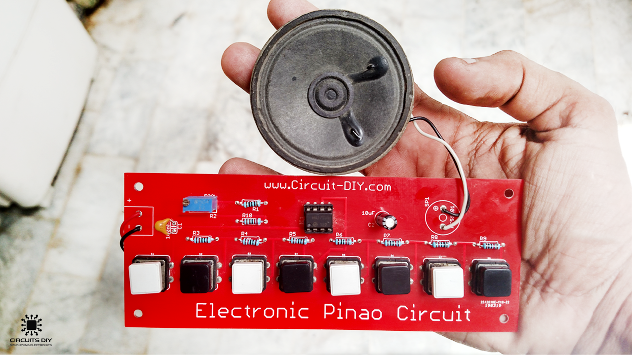
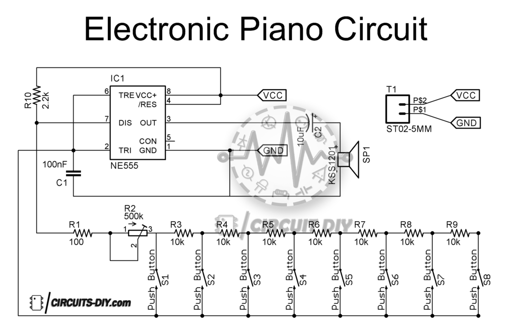
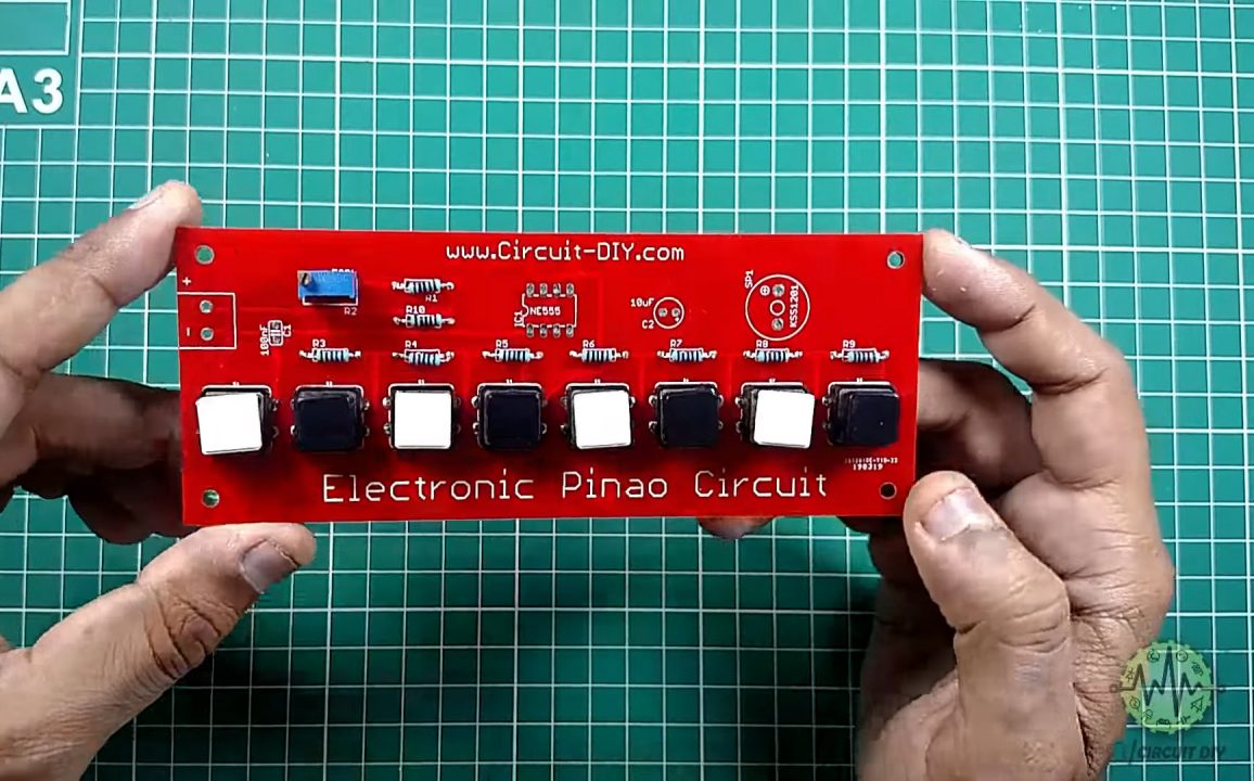
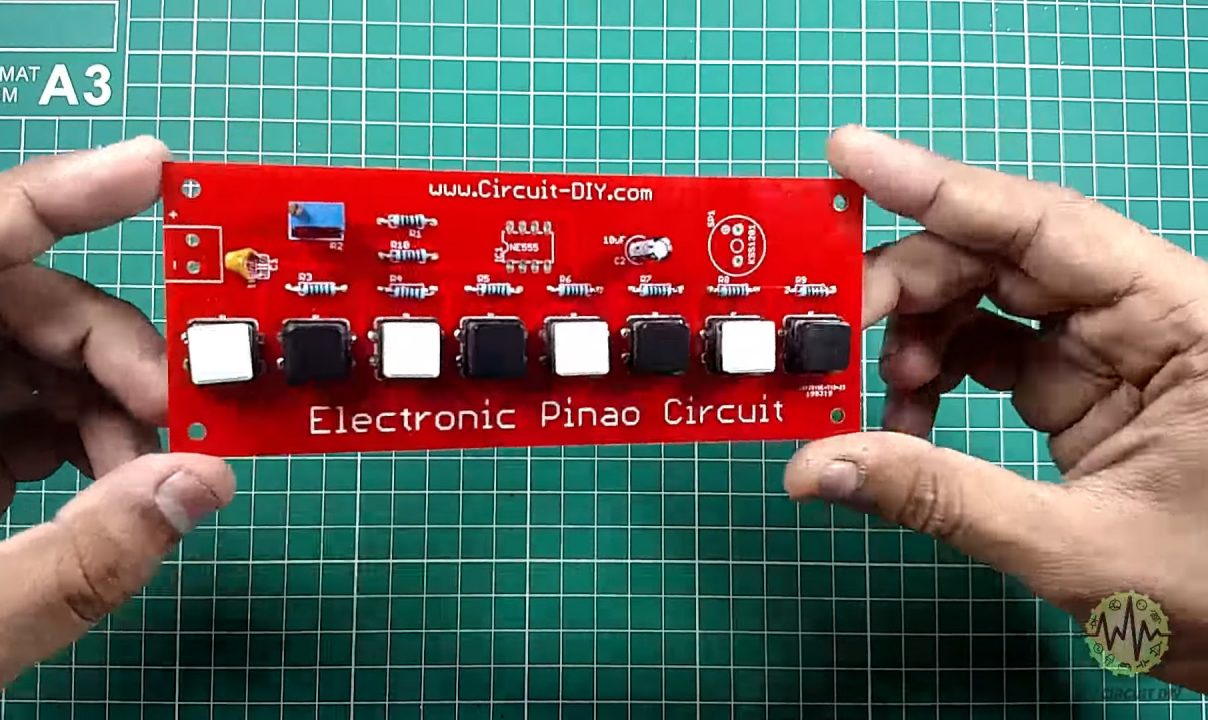
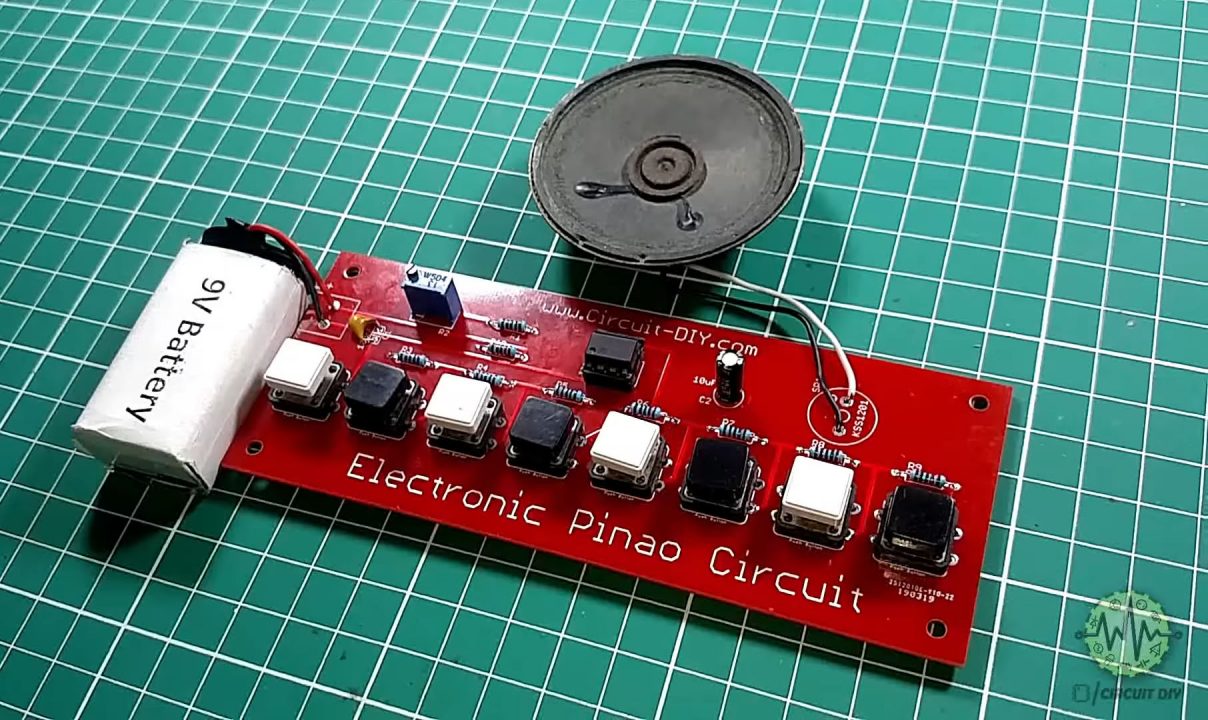
Electronic Piano Circuit
Steps
Make sure to follow each step as shown in the video above
1) Solder all Push buttons onto the PCB Board
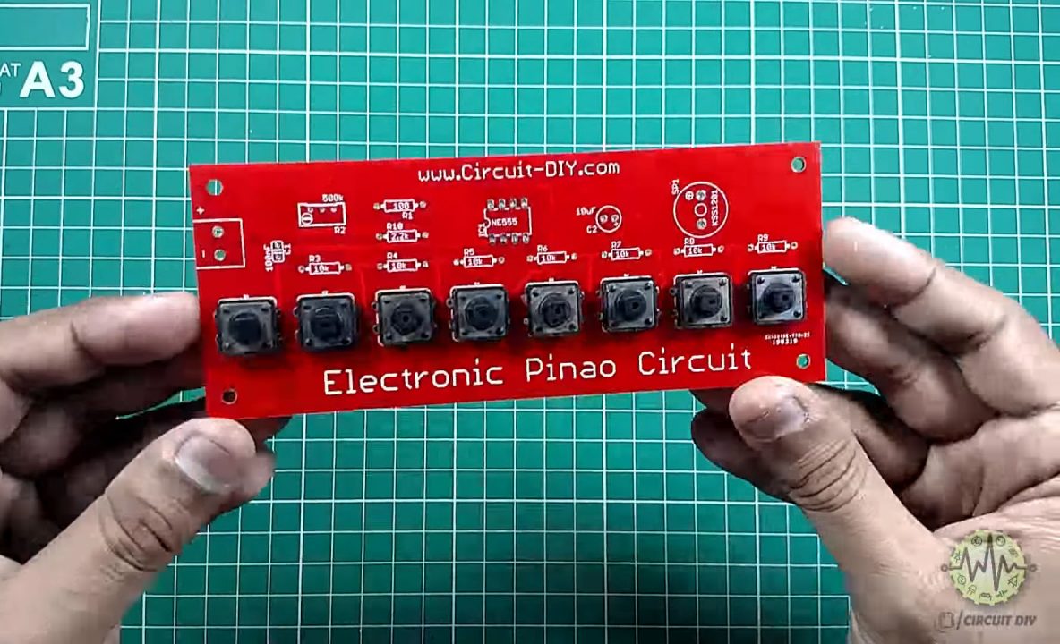
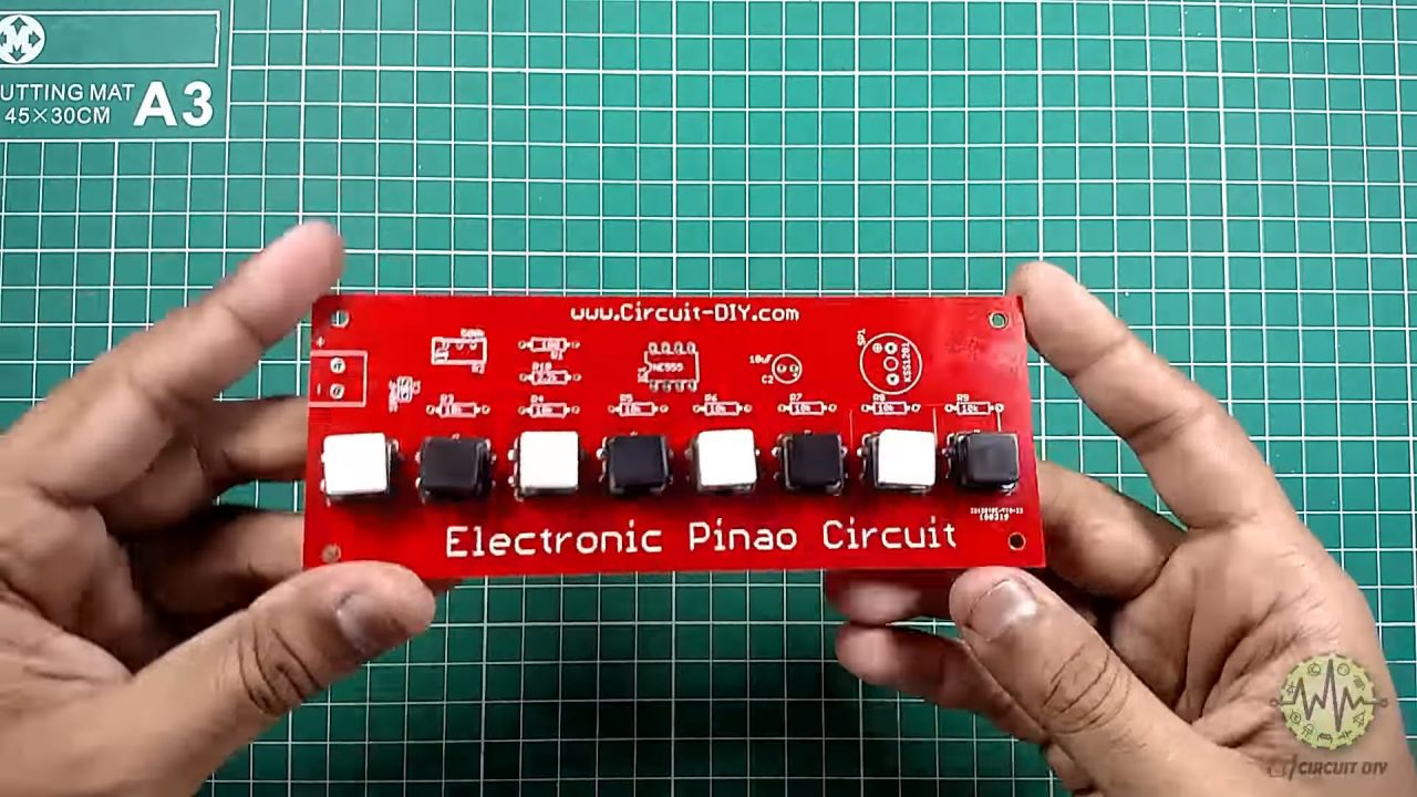
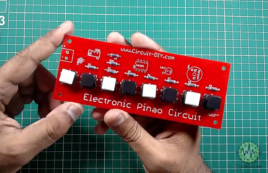
2) Cover all pushbuttons with their Caps
3) Solder all resistors
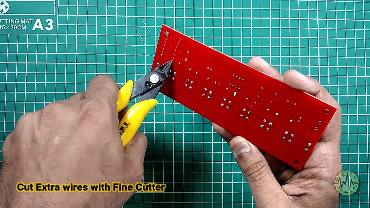
4) Trim any extra wiring.
5) Solder the 500K Trimmer Pot on the PCB Board
6) Solder all capacitors onto the PCB board
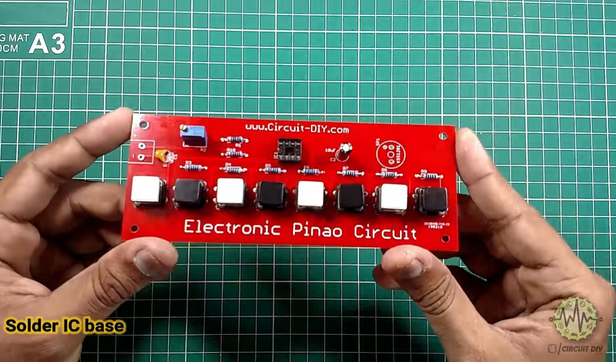
7) Solder the 8-pin IC Jacket onto the PCB Board & Place the IC in the case
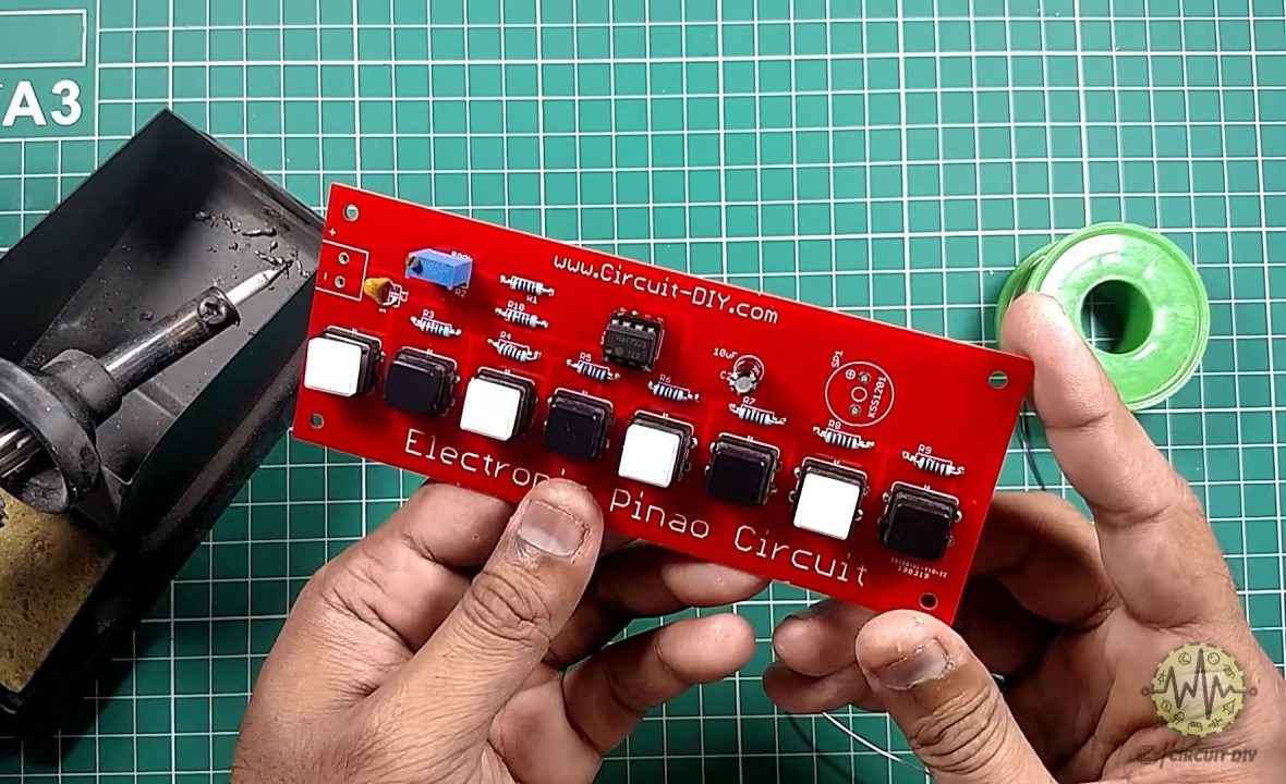
8) Solder the input power connectors (Battery clip) & the output speaker on the PCB Board.
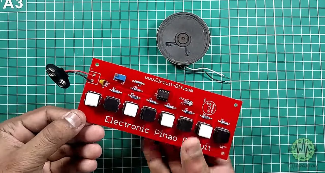
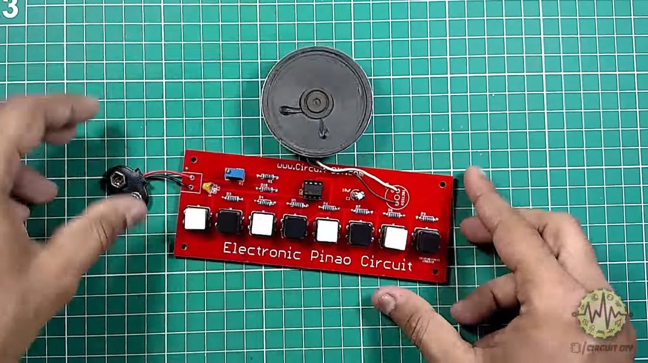
9) Connect the 9V battery & power up the circuit
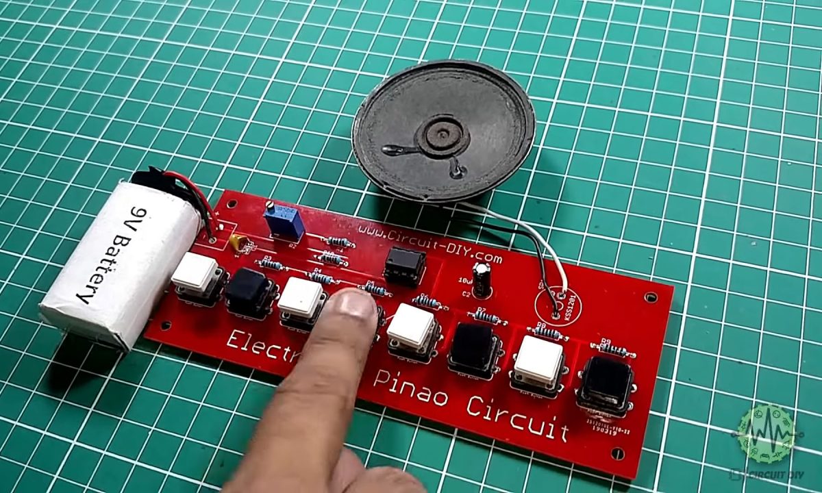
10) test & inspect the circuit.
Working Explanation
The working of this circuit is pretty simple, a total of 8 different switches/pushbuttons are used here to generate different tones which will be fed to the speaker on pressing. a 555 Timer IC is used here to generate tone frequencies of the audible range ( 20Hz to 20KHz ).
When the first button from the right is pressed it produces a high-pitched tone. When the last button is pressed it delivers a low-pitched tone. This is because of the resistance connected to the buttons. The low thresh hold voltage obtained at the Pin 6 slows the charging and discharging of the 10uF capacitor. As the resistance value increases, the voltage at the threshold pin decreases, and low frequency pass through the speaker.
Applications
- Usually used in small devices such as toys, doorbells & alarms, etc.