If you are looking for a project that is fun and fulfills your educative purposes too then this is the ideal project for that. Here is a tutorial on how to make an Electronic number guessing game. This game can be played with multiple players for example your friends or family can play with you. There are ten LEDs in this circuit, marked 1 to 10.
You will choose any random from that and press the switch one time now the LEDs will start rotating for a few seconds and stop on a single LED. So if the number you chose corresponds with the LED blinking, you won.
Hardware Components
The following components are required to make Electronic Number Guessing Circuit
| S.no | Component | Value | Quantity |
|---|---|---|---|
| 1. | DC Supply | 6-12V | |
| 2. | Push button | – | 1 |
| 3. | Transistor | 2N3904 | 1 |
| 4. | IC | NE555 Timer | 1 |
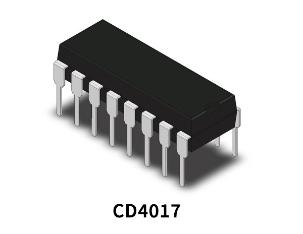
| 5. | Decade Counter IC | CD4017 | 1 |
| 6. | Resistor | 470K, 47K, 4.7K, 1K | 1, 1, 1, 1 |
| 7. | Potentiometer | 100KΩ | 1 |
| 8. | Electrolytic Capacitor | 470µF, 10µF | 1, 1 |
| 9. | Ceramic Capacitor | 0.01µF | 1 |
NE555 IC Pinout

For a detailed description of pinout, dimension features, and specifications download the datasheet of 555 Timer
CD4017 Pinout
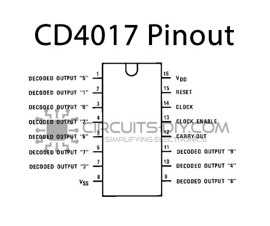
For a detailed description of pinout, dimension features, and specifications download the datasheet of CD4017
Electronic Number Guessing Circuit

Working Explanation
The operating voltage of this circuit is 6 to 12 volts DC. A 2N3904 transistor is used in this circuit along with two ICs (IC1=NE555 & IC2=CD4017) and a few other discrete components. A timer circuit is built around the transistor that will activate the 555 timer IC1 for a few seconds. The 555 timer IC is working as an astable multivibrator and provides positive pulses at the input of IC2. The IC2 is a decade counter IC having 10 outputs, each output has a LED for visual indication.
The output pin, Pin 3 of IC1 is connected with the clock input pin 14 of the IC2. IC2 will activate all the LEDs one by one in sequence on each positive pulse from IC1. After a specific time period, the IC1 will go off and the rotation of the 10 LEDs will stop on any one LED. To control the speed of the rotation we have used a 100K potentiometer. Adjust it for the best results.


