Nowadays the uses of AC wires are pretty common whether it’s our homes, offices, or workplaces. these wires have a tendency to get damaged from the inside due to which the whole system stops working. There are different reasons for this wire damage like aging or short circuits etc. We obviously can not see such issues/damages with the naked eye therefore it is not possible for us to detect where the wire is broken. So to solve these issues we are making an Electric field detector circuit.
It is a very useful circuit to detect electric fields around AC wires, sockets, etc This circuit detects AC voltage in wires without actually touching the wire with an AC meter. This circuit is very effective and useful for those who work with AC or mains voltages it will detect the inside damages in these wires.
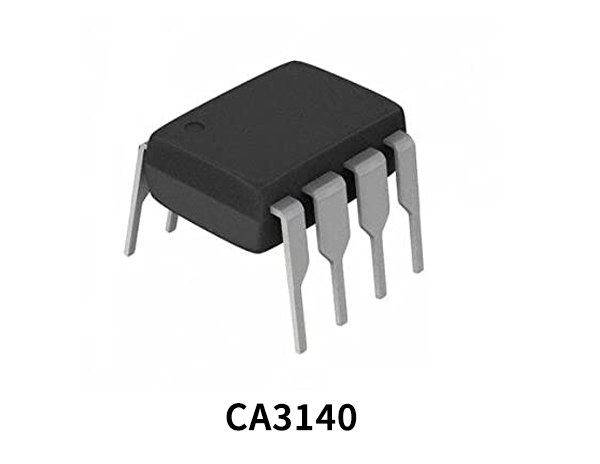
Hardware Components
The following components are required to make a Field Detector Circuit
CA3140 Pinout
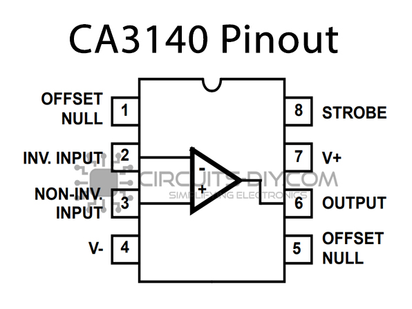
For a detailed description of pinout, dimension features, and specifications download the datasheet of CA3140
Field Detector Circuit

Working Explanation
The working of this circuit is quite simple and easy to build because it uses only a few components. It can be operated at 9 to 12 volts DC. The circuit is highly sensitive, the antenna is used for the detection of the signal from a foot away. It sends the signal to the opamp IC CA310. This IC will give a high signal at its output which will activate the LED.
The LED is used for visual indication of the electric field so that you can be notified when the electric field is detected by the circuit. The sensitivity of this circuit can be increased or decreased by increasing or decreasing the length of the antenna wire. You can further enhance this circuit by using a buzzer or relay instead of an LED.
Application and Uses
- Electric circuits
- House
- Offices
- PCs


