Introduction
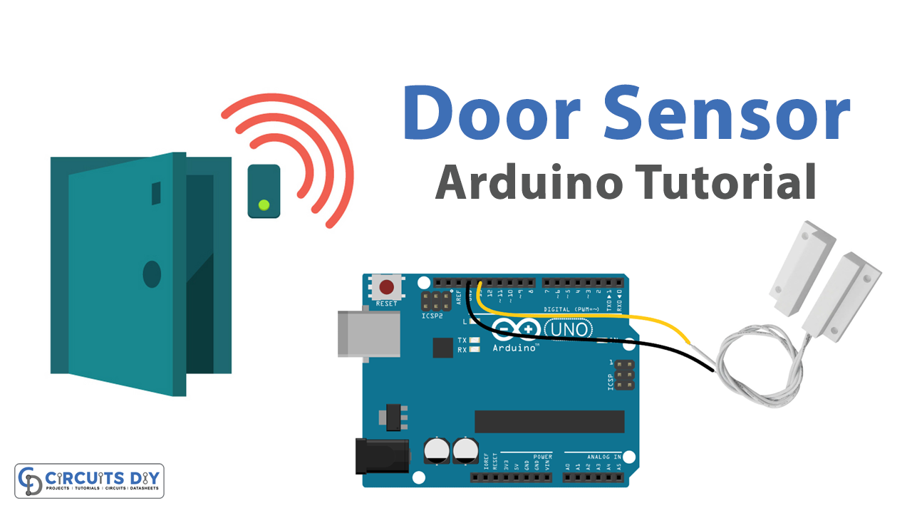
Interfacing a magnetic reed switch door sensor with an Arduino UNO microcontroller is a process of connecting the two devices to perform a specific task. A magnetic reed switch is a type of sensor that detects the presence or absence of a magnetic field. When a magnet is close to the switch, it closes the switch and allows a current to flow. When the magnet is removed, the switch opens and breaks the current.
A magnetic reed switch is a type of electrical switch that uses a magnetic field to control its operation. It consists of a reed element, typically made of a ferromagnetic material, and a fixed magnetic field source. When the magnetic field source is brought close to the reed element, it becomes magnetized and attracts the reed, causing it to move and close an electrical circuit. When the magnetic field is removed, the reed returns to its original position and opens the circuit. Magnetic reed switches are commonly used in various applications such as security systems, door sensors, and automation systems.
Hardware Components
You will require the following hardware for Door Sensor with Arduino.
| S.no | Component | Value | Qty |
|---|---|---|---|
| 1. | Arduino UNO | – | 1 |
| 2. | USB Cable Type A to B | – | 1 |
| 3. | Door Sensor | – | 1 |
| 4. | 9V Power Adapter for Arduino | – | 1 |
Door Sensor with Arduino
- Define the pin connected to the door sensor:
const int DOOR_SENSOR_PIN = 13; // Arduino pin connected to door sensor's pin
The constant integer DOOR_SENSOR_PIN is defined and set to 13, which is the digital pin number on the Arduino that the door sensor is connected to.
- Initialize the door sensor state variable:
int doorState;
A variable doorState is declared to store the state of the door sensor.
- The
setup()function:
void setup() {
  Serial.begin(9600);                     // initialize serial
  pinMode(DOOR_SENSOR_PIN, INPUT_PULLUP); // set arduino pin to input pull-up mode
}
The setup() function initializes serial communication at 9600 bits per second and sets the door sensor pin to input pull-up mode.
- The
loop()function:
void loop() {
  doorState = digitalRead(DOOR_SENSOR_PIN); // read state

  if (doorState == HIGH) {
    Serial.println("The door is open");
  } else {
    Serial.println("The door is closed");
  }
}
The loop() function reads the state of the door sensor using the digitalRead() function and stores it in the doorState variable. Then, it checks if the door state is HIGH or LOW and outputs the corresponding message to the serial monitor. If the door sensor is open, the message “The door is open” will be displayed, and if the door sensor is closed, the message “The door is closed” will be displayed.
Schematic
Make connections according to the circuit diagram given below.

Wiring / Connections
| Arduino | Sensor |
|---|---|
| GND | GND |
| D13 | GIOP |
Installing Arduino IDE
First, you need to install Arduino IDE Software from its official website Arduino. Here is a simple step-by-step guide on “How to install Arduino IDE“.
Code
Now copy the following code and upload it to Arduino IDE Software.
const int DOOR_SENSOR_PIN = 13; // Arduino pin connected to door sensor's pin

int doorState;

void setup() {
  Serial.begin(9600);                     // initialize serial
  pinMode(DOOR_SENSOR_PIN, INPUT_PULLUP); // set arduino pin to input pull-up mode
}

void loop() {
  doorState = digitalRead(DOOR_SENSOR_PIN); // read state

  if (doorState == HIGH) {
    Serial.println("The door is open");
  } else {
    Serial.println("The door is closed");
  }
}
Working Explanation
The setup() function is called once when the sketch starts. In the setup function, the serial communication is initialized with a baud rate of 9600 bits per second. The pin connected to the door sensor is set to input pull-up mode using the pinMode() function.
The loop() function is called repeatedly as long as the Arduino board is powered. It reads the state of the door sensor using the digitalRead() function and stores it in the doorState variable. If the door state is high, the message “The door is open” is printed on the serial monitor. If the door state is low, the message “The door is closed” is printed on the serial monitor.
Applications
- Home security systems
- Automated doors and gates
- Automated lighting control
- Monitoring the status of doors and windows
- Detecting the opening and closing of cabinets and drawers
- Inventory management systems
Conclusion.
We hope you have found this Door Sensor Circuit very useful. If you feel any difficulty in making it feel free to ask anything in the comment section.