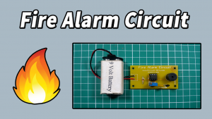
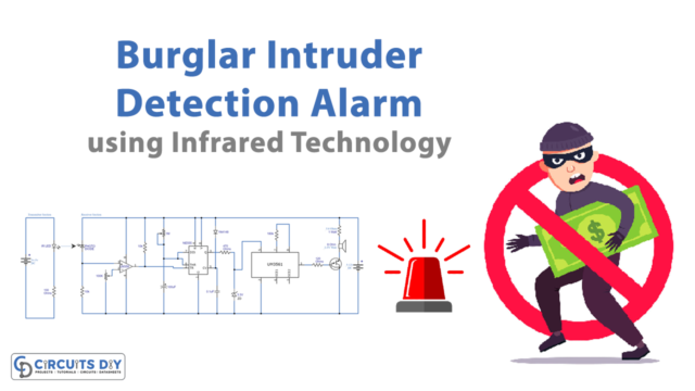
In this tutorial, we are making a project on a door security alarm circuit. This circuit is easy to make, inexpensive and so compact that it can be fitted in a very small place easily. It can be used for different security purposes such as at the door when a burglar or thief tries to break into your house, this circuit will activate the buzzer to alarm you.
The main component of this circuit is a 555 timer IC. This IC is used to provide oscillations and long or short time delays in a circuit. It has three modes of operation i.e., astable, bistable, and monostable. You can choose its operating mode according to the function.

Hardware Components
The following components are required to make Door Security Alarm Circuit
| S.no | Component | Value | Qty |
|---|---|---|---|
| 1. | Input Supply DC | 6-12V | 1 |
| 2. | Reed Switch | – | 1 |
| 3. | Resistor | 10KΩ, 1KΩ | 1 |
| 4. | Potentiometer | 100KΩ | 1 |
| 5. | Electrolytic Capacitor | 10µF | 1 |
| 6. | Buzzer | – | 1 |
| 7. | Ceramic Capacitor | 0.01µF | 1 |
| 8. | IC | NE555 Timer | 1 |
NE555 IC Pinout

For a detailed description of pinout, dimension features, and specifications download the datasheet of 555 Timer
Door Security Alarm Circuit

Working Explanation
The operating voltage of this circuit is 6-12V DC. For detection purposes, we are using a reed switch. A reed switch is a device that senses the magnet. It is of two types i.e., normally open and normally closed switches. In order for this to work a small piece of the magnet is required at the other part of the door to put the reed switch in a normally open state when the door is closed. When the door opens the distance between the magnet and the reed switch increases due to which reed switch will go in the normally closed state and the circuit activates.
Applications and Uses
- Security alarms
- Motion sensor alarm
- Doorbells
- Surveillance purposes


