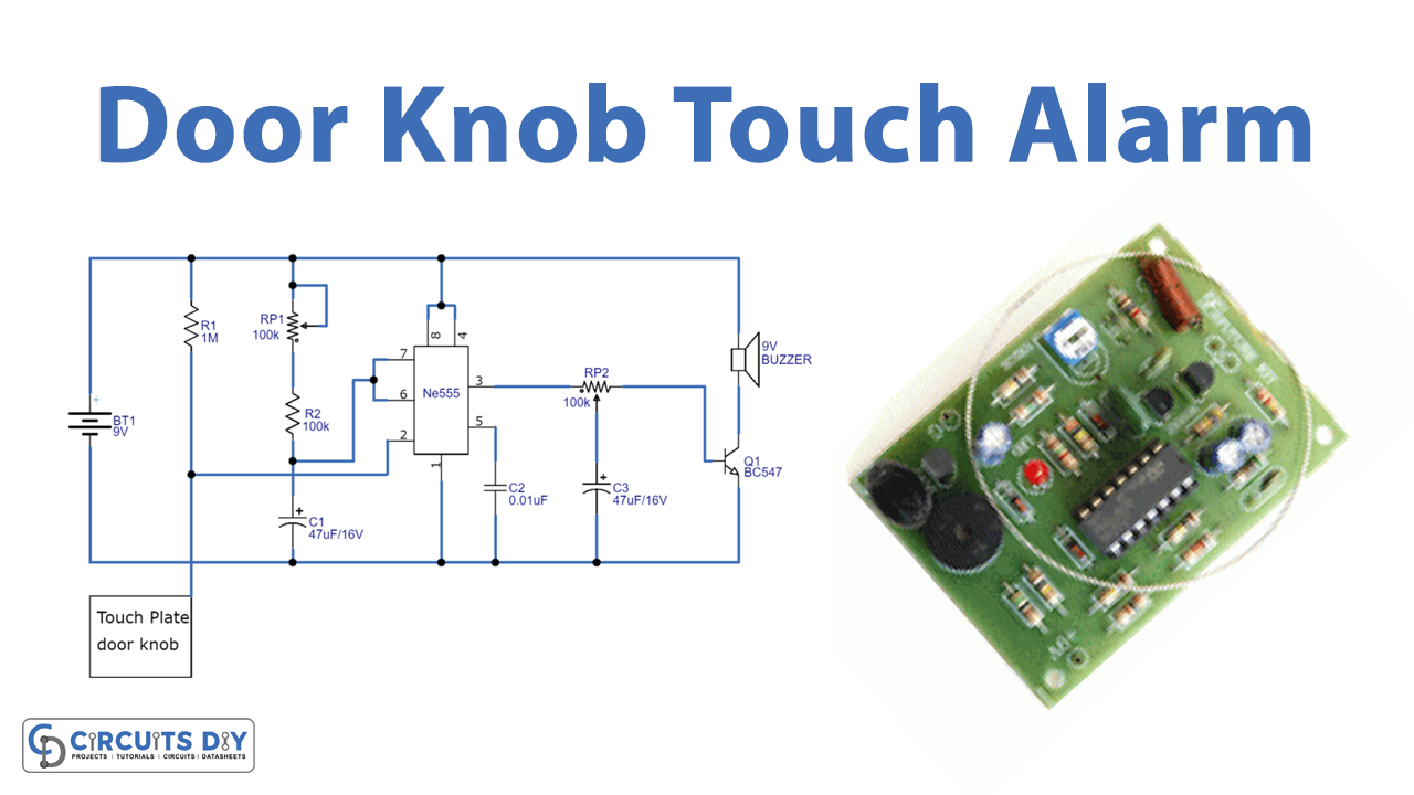
In this tutorial, we are going to make a “Door Knob Touch Alarm Circuit”.
There are many simple alarm devices for personal use in bedrooms or hotel rooms. In which a metal chain attached to a box holding the electronics is placed around the inside doorknob of a wood door. When you touch the sensor of the alarm with your finger and it starts beeping, goes on for some time, and then stops. Touching it again, and it goes again! Here we design a simple doorknob touch alarm circuit by using a timer IC 555 and a few easily available components. When someone touches the doorknob this circuit will give an alert sound, to implement this circuit your doorknob must be a conducting material. In this circuit, the doorknob is used as a touch plate, it acts as a trigger input to the timer IC. To power this circuit, you can use a DC power supply source or a 9 Volt battery.
Hardware Required
| S.no | Component | Value | Qty |
|---|---|---|---|
| 1. | Transistor | BC547 | 1 |
| 2. | IC | NE555 Timer | 1 |
| 3. | Variable Resistor | 100KΩ | 2 |
| 4. | Resistor | 100KΩ, 1MΩ | 1,1 |
| 5. | Capacitor | 47μF / 16V , 0.01μF | 2,1 |
| 6. | Buzzer | 9V | 1 |
| 7. | Connecting Wires | – | – |
| 8. | Battery | 9V | 1 |
Circuit Diagram
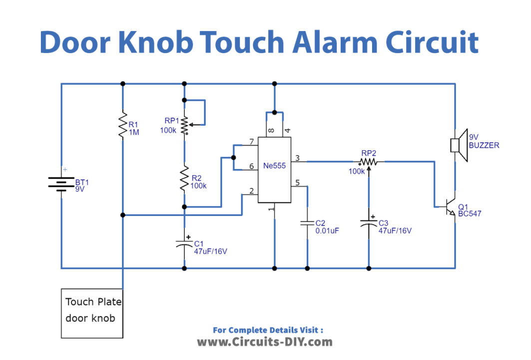
Working Explanation
As shown in the circuit, we have used an IC 555 which acts as a monostable multivibrator. When the trigger pin gets input, it produces a square pulse at the output, and by using the variable resistor VR1 the output pulse duty cycle & duration can be varied. Here through variable resistor VR2, the output pulse from the timer IC555 is given to the transistor base, and the C3 capacitor is connected to the variable pin of VR2. This capacitor is placed to keep transistor Q1 turning ON for a long duration. This circuit will provide a short-duration alarm sound and it can be increased or decreased by the timing components value; you can control any target electrical device by connecting the Relay at the output of the timer IC.
When a person touched the doorknob, it will trigger the timer IC 555. Timer IC starts oscillating square pulse which depends on the timing resistor and timing capacitor value. Now, this pulse drives transistor Q1 and here a buzzer is connected to the Q1 collector. It will get biased when the Q1 gets turned ON.
Applications
It is suitable for simple security applications.