Since doorbells are very common in every house. We know that different types of doorbells are available in the market and they produce different types of music or sound depending on their functionality. These doorbells can be designed using simple electronic components. This article explains a simple circuit that produces a “ding dong doorbell” sound using 555Timer IC.

Hardware Component
The following components are required to make Door Bell Circuit
| S.No | Component | Value | Qty |
|---|---|---|---|
| 1. | Breadboard | – | 1 |
| 2. | Connecting Wires | – | 1 |
| 3. | Battery | 9v | 1 |
| 4. | IC | NE555 Timer | 2 |
| 5. | Electrolytic Capacitor | 100uF | 3 |
| 6. | Ceramic Capacitor | 100nF, 10nF | 1,1 |
| 7. | Variable Resistor | 50k | 1 |
| 8. | Resistors | 330 ohm, 1K, 10K | 1, 2, 1 |
| 9. | Push Button | – | 1 |
| 10. | Speaker | 8 ohm | 1 |
| 11. | LED | 5mm | 1 |
555 IC Pinout

For a detailed description of pinout, dimension features, and specifications download the datasheet of 555 Timer
Door Bell Circuit
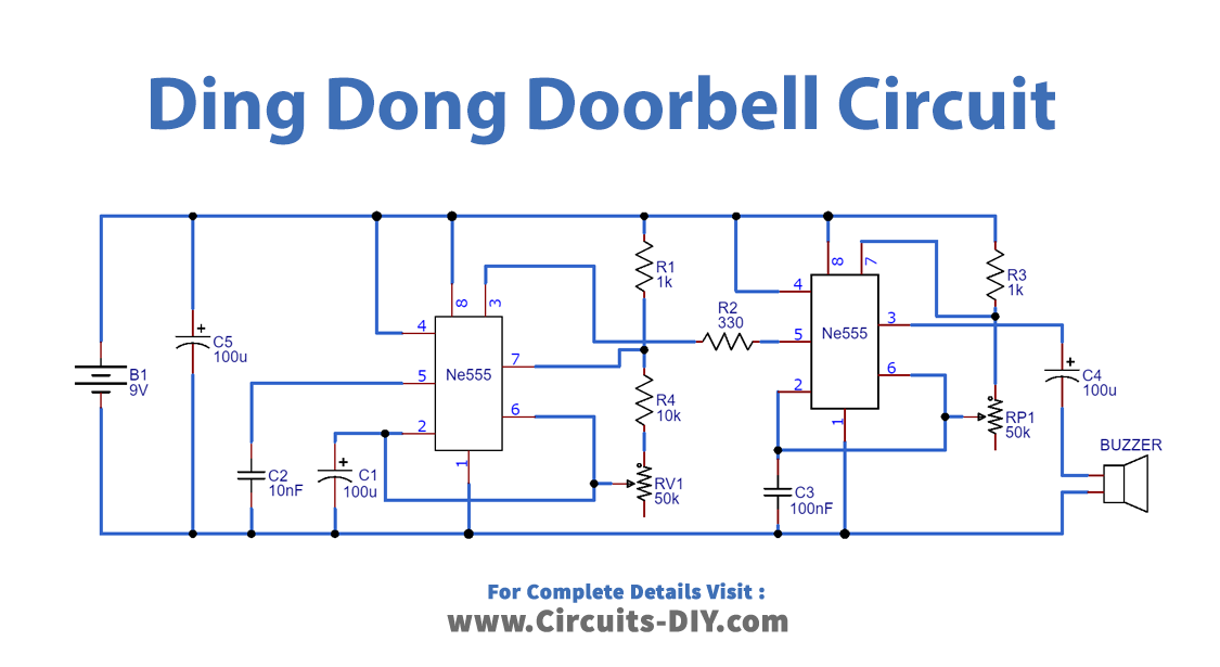
Working Principle
This Ding Dong Sound Generator Door Bell Circuit consists of two 555 timer ICs. The first IC is operated in astable mode and the frequency of the second is modulated by the first IC. For that, the output pin of the first IC is connected with the 5th pin of the second IC.
An astable mode is a free-running mode of the 555 IC. The 555 timer IC can be operated at the desired frequency by tuning the RC circuit. In Astable mode, no external triggering is necessary.
Working Explanation
The working of this circuit can be understood best in the following manner:
- When the power is on, the circuit operates in the astable mode.
- As the voltage is applied to the timer, the capacitor starts charging through R1 and R2.
- When it reaches 2/3 of VCC, it is detected by the sixth pin, and the seventh pin is connected to the ground.
- This way capacitor starts discharging, through the RV1 resistor.
- When the voltage of 1/3 VCC is detected, the capacitor starts charging again.
- This process continuously produces the pulse, which is applied to the second IC through its control pin
- Thus the frequency of the second timer is modulated and applied to the speaker with the help of a capacitor.
The external RC circuit is designed for the specific time delay with which the waveform should be produced. Hence one can hear the “ding dong” sound.
Applications
- As a doorbell
- With some changes, it can be used to produce different sounds.