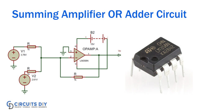
Previously, Op-Amps were developed as analog mathematical calculations and have since been useful in many electrical design applications. However, op-amps are arithmetic voltage calculators. By using a differential amp, they can add two voltage values through the Summing Amplifier circuit and discern between two voltage ranges. Besides, the op-amp is used as inverting amplifiers and non-inverting amps.
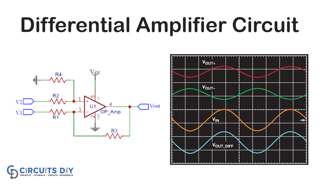
In this DIY tutorial, we will work out how to use an op-amp as a differential amplifier to calculate the voltage difference between two values. We have discovered how to use an op-amp as an amplifier previously. The Voltage Subtractor is also sometimes titled. Moreover, in the end, we will also test a voltage subtractor on the board to verify if the circuit works as intended or not.
Hardware Component
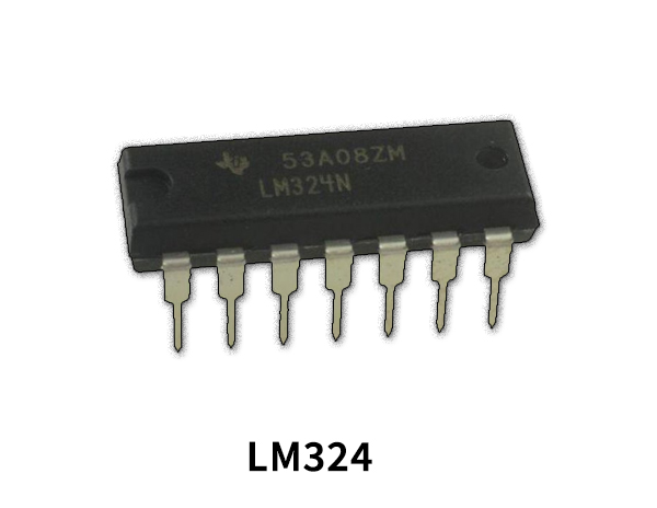
The following components are required to make a Voltage Subtractor Circuit
LM324 Pinout
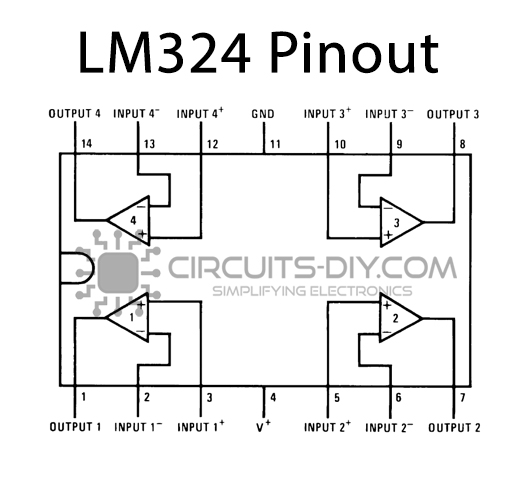
For a detailed description of pinout, dimension features, and specifications download the datasheet of LM324
Voltage Subtractor Circuit
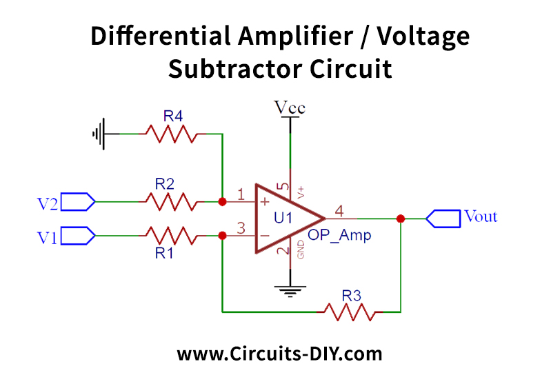
Working Explanation
Let’s now build the same circuit on the breadboard to verify that we have achieved the same performance as we desired. I’ve been designing the circuit with the LM324 Op-Amp, and I’m using the power supply kit that we have developed before in our previous articles. This machine has an output of 5V and a power output of 3.3V, so I can power my op-amp and 3.3V as V1 with a 5V power line. I then used my RPS to provide 3,7 V with the pin V2. Then I used my controlled power supply. We have a voltage difference of 0.4 and 2.2, which should make us 0.88V, and that is exactly what I intended. The illustration below displays the hardware set-up and the 0.88V multimeter reading.
This shows that our interpretation of the differential op-amp is accurate, and we now know how to build differential amplifiers for ourselves with the requisite performance. It is commonly used in volume control circuits.
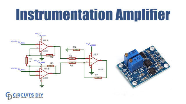
However, because the circuit has input voltage resistors (V1 and V2), the circuit does not have very high input impedance and, therefore, a high typical mode advantage, which results in a low CMRR. However, there is an improvised variant of the differential amplifier known as the instrument amplifier to address these drawbacks.
Applications and Uses
- Generally, it is used as a series negative feedback circuit by using an operational amplifier.
- Generally, we use a differential amplifier that acts as a volume control circuit.
- The differential operational amplifier can likewise be used as an automatic gain control circuit.

