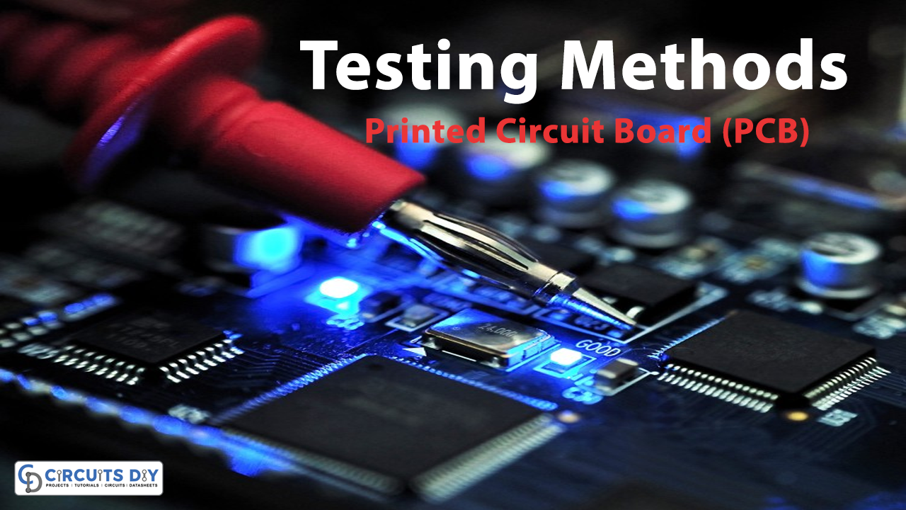
After the manufacturing of Printed circuit boards, the inspection or testing plays a crucial role in the quality game. It checks the errors, vias, connections, and any other related factors. The testing advantages include the reduction of costs, increase safety, identifying bugs, etc. However, there are various methods to choose from for testing. To overview those methods, we are discussing them below.
Flying Probe testing
The flying probe is the most tried PCB testing method. The test carries out through the use of needles that are attached to a probe on an x-y grid got from basic CAD. Your ECM program coordinates to match the circuit board and then runs the program. This testing method is less expensive and we don’t need to make design decisions with the testing in mind. This also can test double-sided printed boards. But, one side at a time with zero issues. However, like the other methods, this testing does not power up the circuit. So one doesn’t get the actual real-world look.
Boundary Scan Testing
We widely used this boundary scan test that looks at the wire lines on Printed circuit boards. The testing tests integrated circuits when it’s not even possible to reach all the nodes of the circuit. In this type of test, they placed the cells in the leads from the silicon to the external pins, to test the functionality of the board. The big discriminating quality is its ability to evaluate a board without reaching all of its nodes. This quality is remarkable for evaluating ICs with multiple layers. Hence, this test has become more common in recent years.
Automated Optical Inspection
In automated inspection methods, they used 2D or 3D cameras and a light source to take proper photographs of the board and then compare them to a schematic. If the two don’t match to a certain degree, an associate flag and examine the board manually. one should use the AOI method in conjunction with another test and should not completely rely on this method.
X-Ray Inspection
X-Ray inspection, which is also known as AXI inspection is a type of testing that can locate hidden features within a target object. During this test, an X-ray operator can locate defects early during the manufacturing process by examining, solder connections, barrels, and internal traces.
In-Circuit Testing
ICT, in-circuit testing, is the most robust type of PCB testing at present, having great potential. The ICT testing system contains testers that involve a matrix of hundreds f drivers and sensors, perform the measurements for the test, a fixer that connects to the in-circuit tester, and is the component that interacts directly with the board being tested, and software that instructs the entire system what tests to perform for each type of board and guides the parameters for a pass or fails.


