Introduction
Sometimes you may have observed that when we give supplies to our electronic or electrical appliances, they take some time duration to turn ON. For instance, when you give power to the refrigerator, washing machine, or other heavy appliances, they take time while turn on. This is because of the delay timer protection circuit.
The circuit protects the devices from sudden unstable or high voltages that can harm the devices and the environment. So, in this tutorial, we have decided to make this worthy “Delay Timer Circuit. The circuit uses IRFZ44N MOSFET as its major component.
Hardware Components
The following components are required to make Delay Timer Circuit
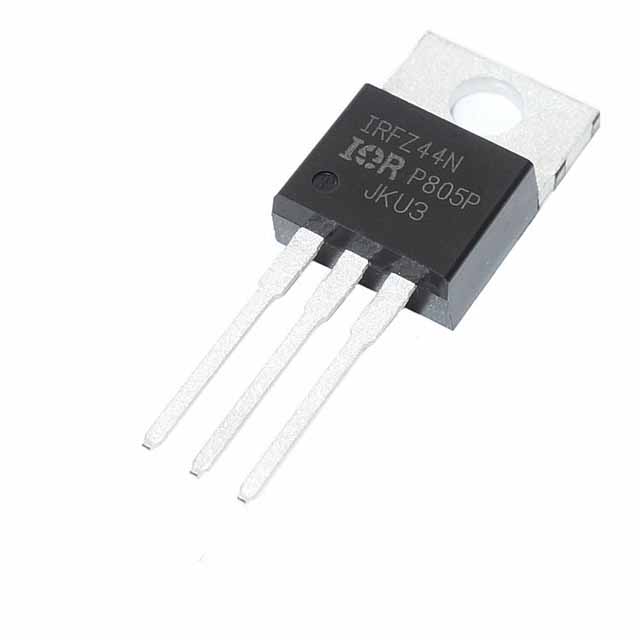
IRFZ44N Pinout
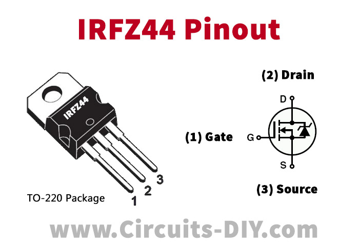
For a detailed description of pinout, dimension features, and specifications download the datasheet of IRFZ44N
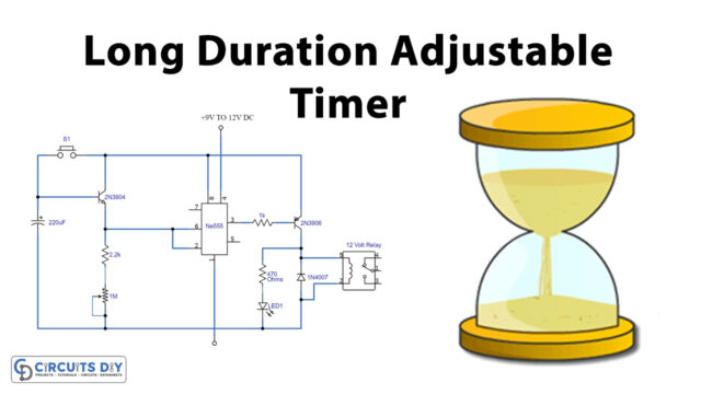
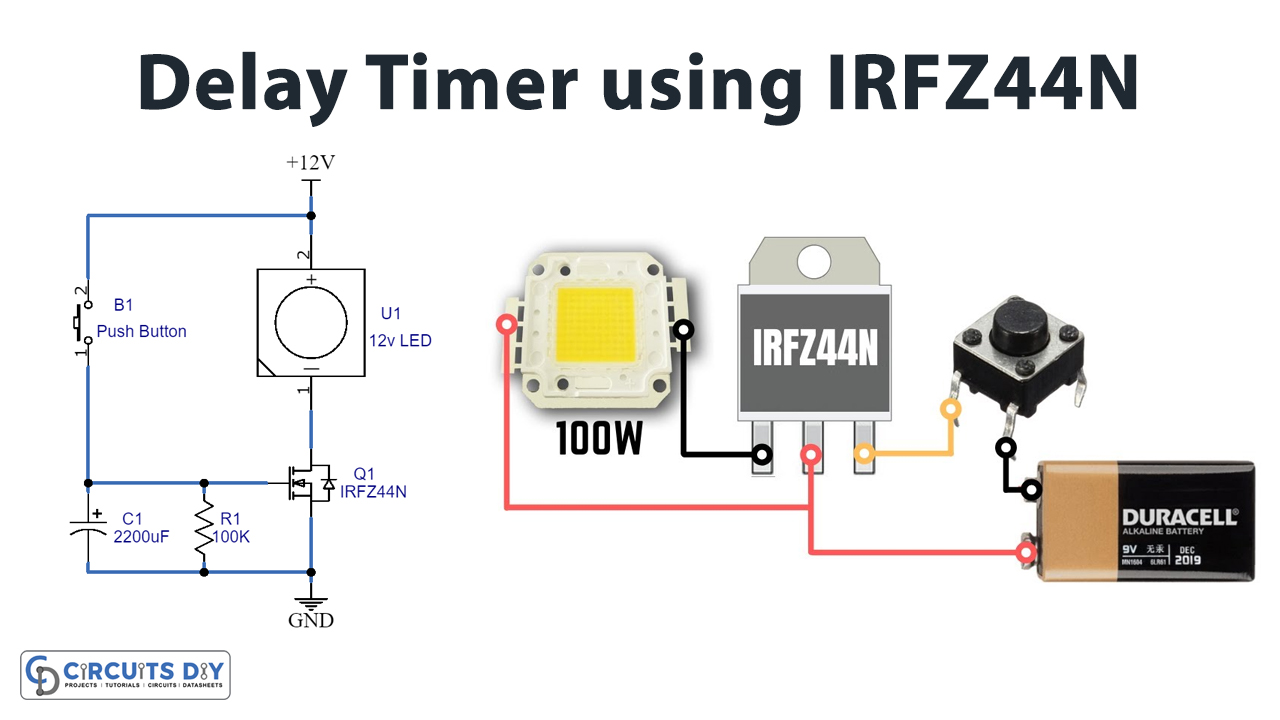
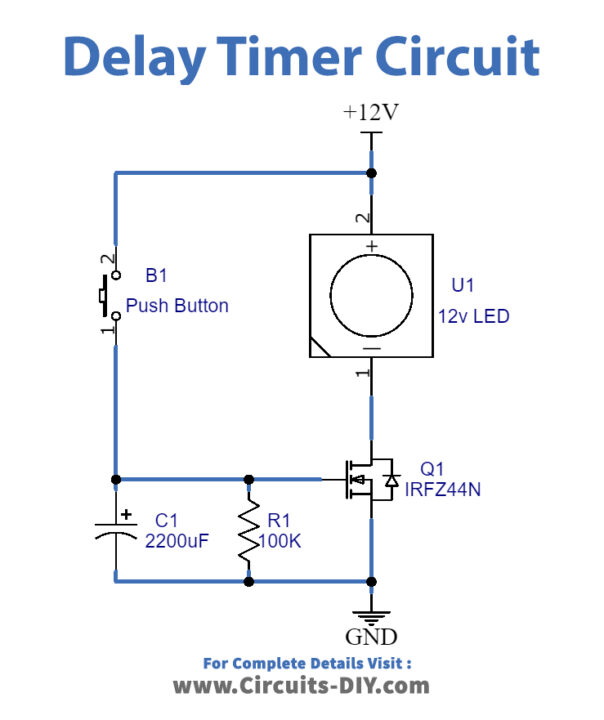
Delay Timer Circuit
Working Explanation
In this Delay Timer Circuit, when the supply is given and you press the push button, the current starts to flow from Vcc to the ground through the 220uf Capacitor. Hence, capacitor charges. When you unpress the push button, the capacitor starts discharging through the MOSFET gate, triggering the MOSFET, and the current starts flowing from source to drain. Therefore, the load gets the power and here our load is the 12V LED.
Application and Uses
- For the protection of electrical and electronic appliances.
- In power supply protection systems, etc