Unlike AC motors, DC motors are very easy to use because their speed can be changed easily. So, how is this achieved in practice? As DC motors generate torque by a reaction between two magnetic fields: one field established by stationary “field” windings (coils), and the other by windings in the rotating armature. Some DC motors lack field windings, substituting large permanent magnets in their place so that the stationary magnetic field is constant for all operating conditions.
In any case, the operating principle of a DC electric motor is that currently passed through the armature creates a magnetic field that tries to align with the stationary magnetic field. This causes the armature to rotate. Here we design a simple circuit using timer IC 555 and MOSFET IRF 540 for DC motor speed control. Some DC motors have unfit RPM (rotation per minute) for projects to control the speed of DC motors this simple circuit can be used.
Hardware Required
| S.no | Component | Value | Qty |
|---|---|---|---|
| 1. | IC | NE555 Timer | 1 |
| 2. | MOSFET | IRF540 | 1 |
| 3. | Diode | 1N4001 | 1 |
| 4. | Motor | – | 1 |
| 5. | Resistor | 47KΩ,560Ω,10KΩ | 1,1,1 |
| 6. | Variable Resistor | 100KΩ | 1 |
| 7. | Capacitor | 0.47uF,1000uF | 1,1 |
| 8. | Connecting Wires | – | |
| 9. | Battery | 12V | 1 |
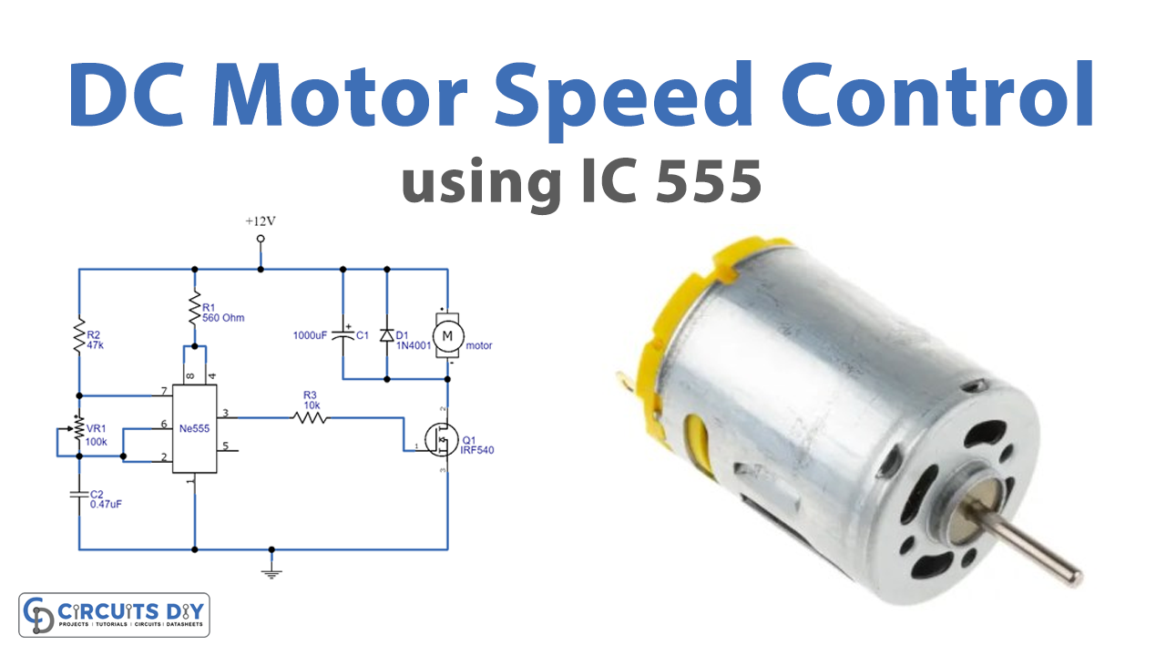
Circuit Diagram

Working Explanation
As we can see in the circuit, the DC bias of 12 volts is directly fed to the DC motor and limited by the R1 resistor. When then applied to timer IC 555, the control voltage pin5 of IC is not connected with any components. Here timing components VR1, and C2 are connected between pin7 and threshold, trigger pins. The output is taken from pin3 and connected with the gate terminal of MOSFET. Further, a diode D1 is placed to protect the motor from back emf.
Now when we give supply to this circuit, the timer IC produces a timing pulse at pin3. This pulse duration depends on VR1 and C2, this timing pulse controls the MOSFET. So the motor connected through MOSFET is controlled, and the pulse output from IC 555 is the reason for the control of the DC motor speed. Therefore by varying the pulse duration we can control the speed of the DC motor. If you are using a microcontroller means you can bias this timer IC through a microcontroller GPIO pin. And then you can control the speed of the motor only by varying the VR1 resistor.
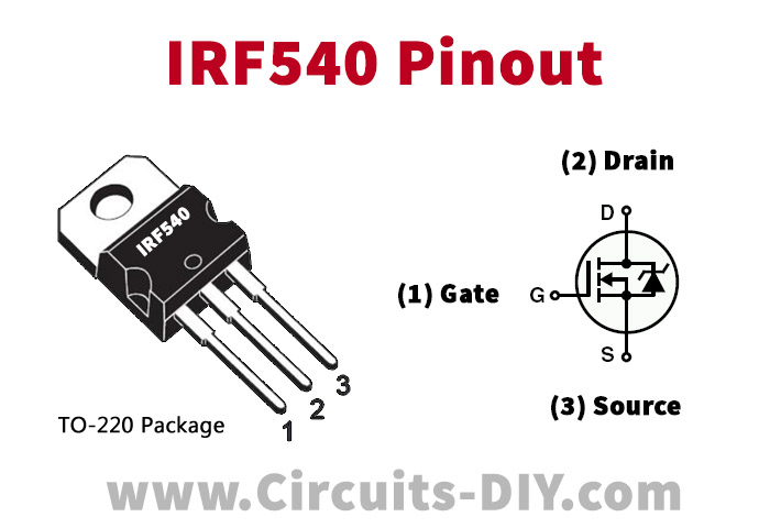
IRF540 Pinout
Applications
- centrifugal and reciprocating pumps
- conveyors, hoists, elevators, and electric Locomotives
- Also can be used in blowers, fans, drilling machines, milling machines, and machine tools


