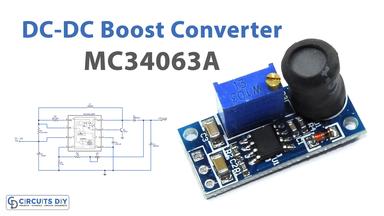
In this tutorial, we are going to make a “DC-DC Boost Converter using MC34063A IC”. A DC-to-DC boost converter steps up voltage (while stepping down current), from its input supply to its output load. It is a class of switched-mode power supply (SMPS), containing at least two semiconductors a diode and a transistor. And at least one energy storage element: a capacitor, inductor, or the two in combination. Boost converters are highly nonlinear systems and a wide variety of linear and nonlinear control techniques, for achieving good voltage regulation with large load variations. Here a DC-DC boost converter circuit is designed by using IC MC34063A.
The MC34063A series is a monolithic control circuit, containing the primary functions required for DC-to-DC converters. It is a control circuit with integrated chips, that can buck, boost and invert voltages. It has a switching frequency of up to 100 kHz. Due to its voltage conversion property, you can adjust its output voltage by only two external resistors. It operates in a temperature range of 0 °C to 70 °C. This IC requires a minimum number of external components, for step-up, step-down, and voltage inverting operations. This circuit is designed to give 12V/1.5A output, from a minimum of 5V DC.
Hardware Required
| S.no | Component | Value | Qty |
|---|---|---|---|
| 1. | IC | MC34063A | 1 |
| 2. | Transistor | TIP31 | 1 |
| 3. | Diode | MBR340 | 1 |
| 4. | Inductor | 100uH | 1 |
| 5. | Resistor | 0.33Ω,180Ω,1.5KΩ,12KΩ | 1,1,1,1 |
| 6. | Capacitor | 100uf,0.001uf,2200uf | 1,1,1 |
| 7. | Variable Resistor | 1KΩ | 1 |
| 8. | Connecting Wires | – | – |
| 9. | Battery | 12V | 1 |
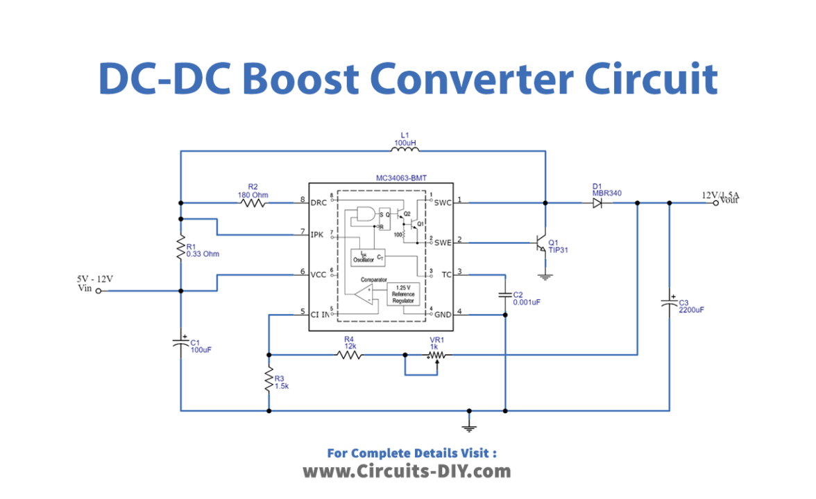
Circuit Diagram
MC34063A Pinout

Working Explanation
As we can see, the main part of this circuit is a step-up DC-DC converter IC MC34063A. It is capable of taking input from 3.0V to 40V and gives an output current range of up to 1.5A, with adjustable output voltage. And also it has a current limiting possibility and low standby current. Here values of R1 and R2 resistors are responsible for internal oscillating frequency. And VR1 takes control of efficiency because it is connected between the output and internal comparator. Now L1 is 100µH or you can make a core coil with 30 turns of 22 AWG, and the MBR340 Schottky barrier rectifier gives pure DC at the output.
Applications
This circuit can be used for step-up DC supply from batteries.