In this tutorial, we are making a project of a daytime car headlight switch-on reminder. During the daytime, we often need to open the car headlights but forget to turn them off and they are not even that visible in daylight anyway so you wouldn’t know.
As a result, this consumes the car’s battery fully due to which the car doesn’t start and becomes deeply discharged. To get away with all these issues this circuit will always come in handy. It will give a beep signal after signal during the daytime to remind you if the headlights are ON, this circuit will automatically deactivate during night time it is just for the daytime or in lightning conditions as it’s working on the basis of a photoresistor.

Hardware Components
The following components are required to make Car Headlights Switch Circuit
| S.no | Component | Value | Qty |
|---|---|---|---|
| 1. | Input Supply Voltage | 12V | 1 |
| 2. | LDR | – | 1 |
| 3. | Variable resistor | 100K | 2 |
| 4. | Resistor | 1K, 10K | 2, 1 |
| 5. | Electrolytic Capacitor | 10uF | 1 |
| 6. | Ceramic Capacitor | 0.01uF | 1 |
| 7. | IC | NE555 Timer | 1 |
| 8. | Buzzer | – | 1 |
| 9. | Transistor | 2N3904 | 1 |
NE555 IC Pinout
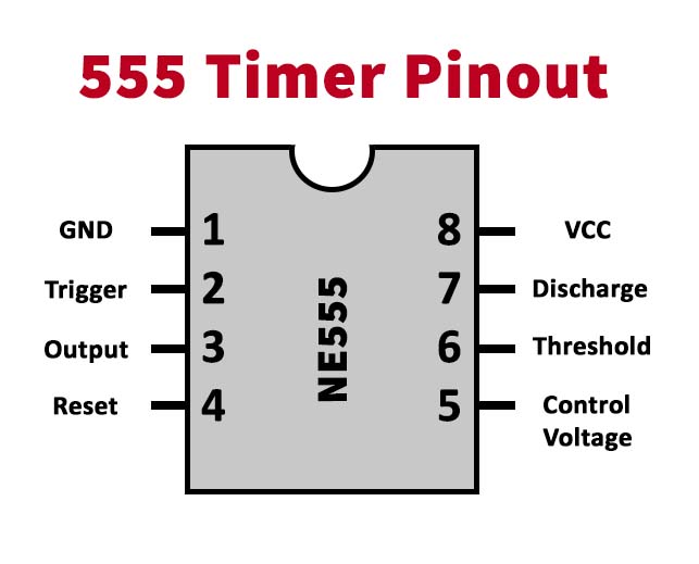
For a detailed description of pinout, dimension features, and specifications download the datasheet of 555 Timer
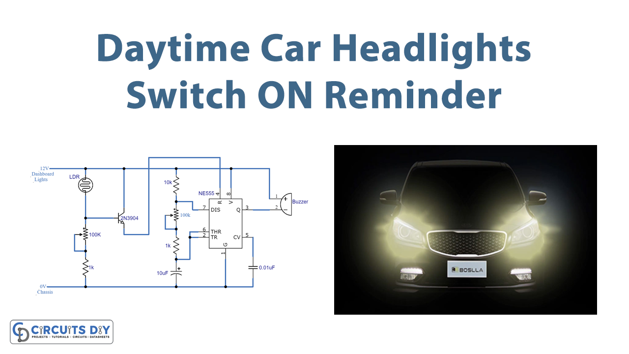
Car Headlights Switch Circuit
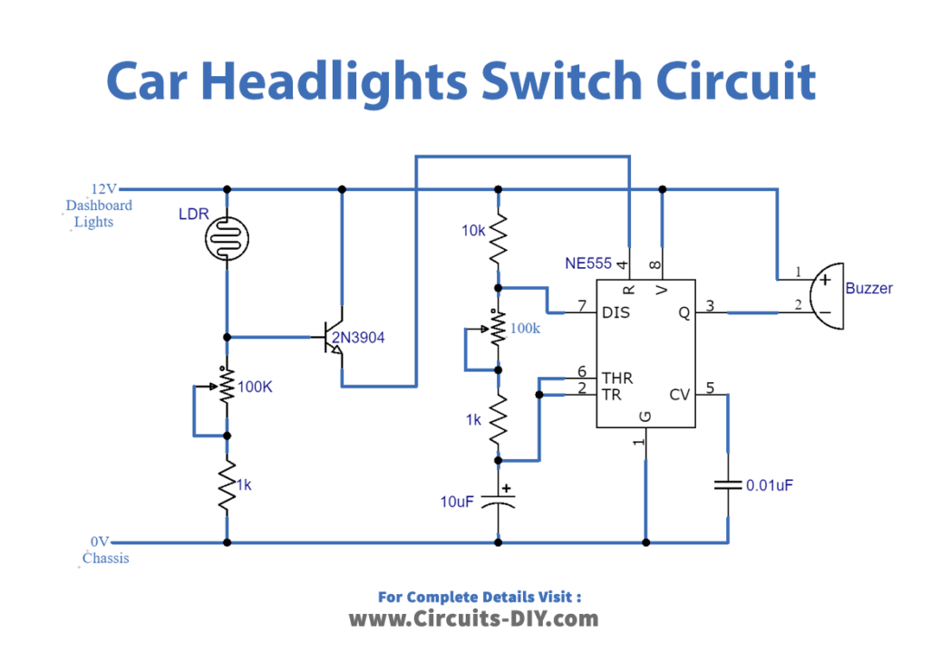
Working Explanation
The operating voltage of this circuit is 12 volts DC and it is connected to the dashboard lights and chassis of the car. The LDR should be placed where it can receive daylight easily. Adjust the variable resistor to activate the circuit at the desired level of light. When the LDR receives light it will activate the transistor and the IC will be activated too. Now the 555 timer IC will send a high signal for a specific time period to the buzzer and it will produce a beep sound, the IC will keep providing a high low signal until the LDR senses no light around it and the circuit deactivates. The time gap between each beep or high signal is adjusted by the other variable resistor used at 555 IC.

