The dark detector, as its name suggests, detects darkness, in a room. The circuit involved in dark detection is very simple and cost-effective. The main part includes the photoresistor, while, the others are a diode, relay, and transistor.

Hardware Components
The following components are required to make Dark Detecting Circuit
| S.no | Component | Value | Qty |
|---|---|---|---|
| 1. | Transistor | 2N2222 | 1 |
| 2. | Relay | – | 1 |
| 3. | Battery | 6V | 1 |
| 4. | Diode | 1N4001 | 1 |
| 5. | Photoresistor | – | 1 |
| 6. | Resistor | 1KΩ | 1 |
| 7. | Variable resistor | 50K | 1 |
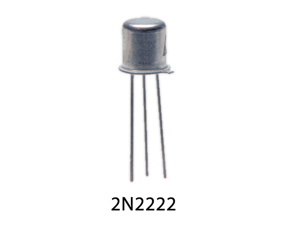
2N2222 Pinout

For a detailed description of pinout, dimension features, and specifications download the datasheet of 2N2222
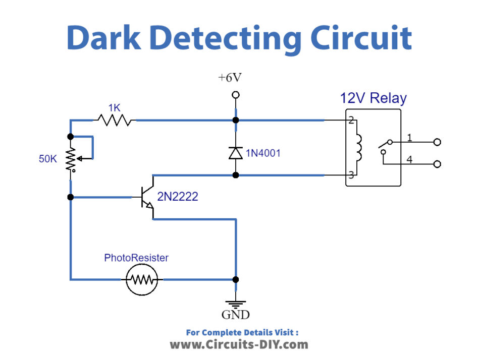
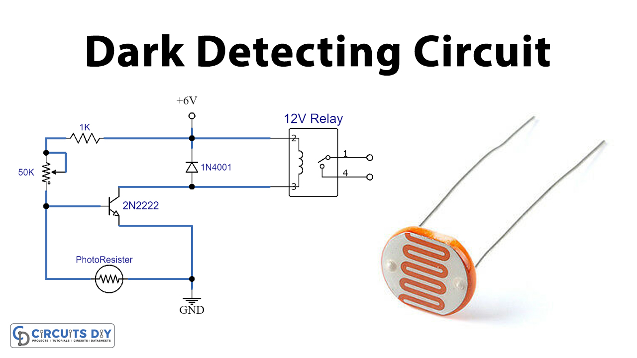
Dark Detecting Circuit

Working Explanation
This circuit works such that the photoresistor, at first, will detect light. The base of the phototransistor is exposed to the environment. Thus, the photons from light strike the base of the photoresistor. When there is no light, a signal is produced by the phototransistor that will trigger the 2N2222 transistor. The transistor is responsible to activate the relay.
The sensitivity of the overall circuit adjusts through the variable resistor 50KΩ. Moreover, the relay used in the circuit is of the same voltage as that of the battery.
Application
- Automation of homes or rooms that is whenever the room is dark, the circuit lights up
- Home security system


